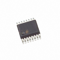
ISL6742AAZA-T Intersil, ISL6742AAZA-T Datasheet - Page 6

ISL6742AAZA-T
Manufacturer Part Number
ISL6742AAZA-T
Description
IC CTRLR PWM DBL ENDED 16-QSOP
Manufacturer
Intersil
Datasheet
1.ISL6742AAZA.pdf
(18 pages)
Specifications of ISL6742AAZA-T
Pwm Type
Voltage/Current Mode
Number Of Outputs
4
Frequency - Max
2MHz
Duty Cycle
100%
Voltage - Supply
9 V ~ 16 V
Buck
No
Boost
No
Flyback
No
Inverting
No
Doubler
No
Divider
No
Cuk
No
Isolated
No
Operating Temperature
-40°C ~ 105°C
Package / Case
16-QSOP
Frequency-max
2MHz
Lead Free Status / RoHS Status
Lead free / RoHS Compliant
Other names
ISL6742AAZA-TTR
Available stocks
Company
Part Number
Manufacturer
Quantity
Price
Company:
Part Number:
ISL6742AAZA-T
Manufacturer:
Intersil
Quantity:
2 000
Part Number:
ISL6742AAZA-T
Manufacturer:
INTERSIL
Quantity:
20 000
Electrical Specifications
RAMP
RAMP Sink Current Device Impedance
RAMP to PWM Comparator Offset
Bias Current
Clamp Voltage
SOFT-START
Charging Current
SS Clamp Voltage
SS Discharge Current
Reset Threshold Voltage
ERROR AMPLIFIER
Input Common Mode (CM) Range
GBWP
VERR VOL
VERR VOH
VERR Pull-Up Current Source
EA Reference
EA Reference + EA Input Offset Voltage
PULSE WIDTH MODULATOR
Minimum Duty Cycle
Maximum Duty Cycle (Per Half-cycle)
Zero Duty Cycle VERR Voltage
VERR to PWM Comparator Input Offset
VERR to PWM Comparator Input Gain
Common Mode (CM) Input Range
OSCILLATOR
Frequency Accuracy, Overall
Frequency Variation with VDD
Temperature Stability
Charge Current
Discharge Current Gain
PARAMETER
6
Recommended operating conditions unless otherwise noted. Refer to “Functional Block Diagram” on page 2,
“Typical Application - Telecom Primary Side Control Half-Bridge Converter with Synchronous Rectification” on
page 3 and “Typical Application - High Voltage Input Secondary Side Control Full-Bridge Converter” on page 4.
9V < VDD < 20V, RTD = 10.0kΩ, CT = 470pF, T
Parameters with MIN and/or MAX limits are 100% tested at +25°C, unless otherwise specified. Temperature
limits established by characterization and are not production tested. (Continued)
V
T
V
(Note 3)
SS = 3V
SS = 2V
T
(Note 3)
(Note 3)
I
I
VERR = 2.50V
T
VERR < 0.6V
VERR = 4.20V, V
V
RTD = 2.00kΩ, CT = 220pF
RTD = 2.00kΩ, CT = 470pF
T
(Note 3)
(Note 3)
T
VDD = 10V, |F
(Note 3)
|F
(Note 3)
T
LOAD
LOAD
A
A
A
A
A
A
RAMP
RAMP
CS
0°C
= +25°C
= +25°C
= +25°C
= +25°C
= +25°C, (F
= +25°C, V
= 0V (Note 4)
- F
= 2mA
= 0mA
= 0.3V
= 1.1V
105°C
TEST CONDITIONS
CS
-40°C
|/F
ISL6742
20V
25°C
RAMP
= 1.8V
- - F
- F
10V
0°C
= 0V,
)/F
|/F
10V
0°C
A
= -40°C to +105°C, Typical values are at T
4.410
0.594
0.590
0.23
4.20
0.85
0.31
-193
MIN
-5.0
165
-60
-10
6.5
0.8
0.7
65
10
19
0
5
0
-
-
-
-
-
-
-
-
-
4.500
0.600
0.600
TYP
0.27
0.33
-200
183
-70
1.0
0.8
0.3
4.5
1.5
80
94
97
99
21
-
-
-
-
-
-
-
-
-
-
-
-
VREF
4.590
0.606
0.612
MAX
-207
0.33
1.20
0.35
4.45
-2.0
201
+10
8.0
-80
0.4
1.3
0.9
1.7
20
95
23
0
-
-
-
-
-
-
-
-
A
= +25°C.
October 31, 2008
UNITS
µA/µA
MHz
kHz
V/V
mV
mA
mA
µA
µA
µA
FN9183.2
%
%
%
%
%
%
%
%
Ω
V
V
V
V
V
V
V
V
V
V
V


