ISL6224CA Intersil, ISL6224CA Datasheet
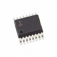
IC CONTROLLER PWM SINGLE 16-SSOP

ISL6224CA

Manufacturer Part Number
ISL6224CA
Description
IC CONTROLLER PWM SINGLE 16-SSOP
Manufacturer
Intersil
Datasheet

Specifications of ISL6224CA

Pwm Type
Current Mode
Number Of Outputs
1
Frequency - Max
690kHz
Duty Cycle
94%
Voltage - Supply
4 V ~ 24 V
Buck
Yes
Boost
No
Flyback
No
Inverting
No
Doubler
No
Divider
No
Cuk
No
Isolated
No
Operating Temperature
-10°C ~ 85°C
Package / Case
16-QSOP
Frequency-max
690kHz
Lead Free Status / RoHS Status
Contains lead / RoHS non-compliant

Available stocks

Company
Part Number
Manufacturer
Quantity
Price
Part Number:
ISL6224CA
Manufacturer:
INTERSIL
Quantity:
20 000
Company:
Part Number:
ISL6224CA
Quantity:
41
Part Number:
ISL6224CA-T
Quantity:
15
Part Number:
ISL6224CA-T
Manufacturer:
INTERSIL
Quantity:
1 275
Part Number:
ISL6224CAZ
Manufacturer:
INTERSIL
Quantity:
20 000
Part Number:
ISL6224CAZ-T
Manufacturer:
INTERSIL
Quantity:
6 387
Single Output Mobile-Friendly PWM
Controller
The ISL6224 provides power control and protection for a single,
adjustable output voltage required to power chip-sets and
memory banks in high-performance notebooks and PDAs. This
output voltage is adjustable in the range from 0.9-5.5V.
The hysteretic or PWM controller regulates the output
voltage from battery voltages ranging from 4V to 24V.
Synchronous rectification and hysteretic operation at light
loads contribute to a high efficiency over a wide range of
input voltages and loads. Efficiency is even further enhanced
by using MOSFET’s r
Feed-forward ramp modulation, average current mode
control and internal feed-back compensation provide fast
and firm handling of transients when powering advanced
chip sets.
Two-stage conversion using system 5V voltage is possible at
a higher frequency (600kHz) to minimize the output filter size.
The ISL6224 monitors the output voltage. A PGOOD (power
good) signal is issued when soft-start is completed and the
output is within ±10% of the set point.
A built-in overvoltage protection prevents output voltage
from going above 120% of the set point. Undervoltage
protection latches the chip off when the output drops below
70% of its setting value after soft-start sequence is
completed. The PWM controller’s overcurrent circuitry
monitors the output current by sensing the voltage drop
across the lower MOSFET. If higher precision sense
technique is required, an optional external current-sense
resistor may be used.
Ordering Information
NOTES:
ISL6224CA
ISL6224CAZ
(Note 1)
1. Intersil Pb-free plus anneal products employ special Pb-free
2. Add “-T” for Tape and Reel.
NUMBER
PART
material sets; molding compounds/die attach materials and
100% matte tin plate termination finish, which are RoHS
compliant and compatible with both SnPb and Pb-free soldering
operations. Intersil Pb-free products are MSL classified at
Pb-free peak reflow temperatures that meet or exceed the
Pb-free requirements of IPC/JEDEC J STD-020.
ISL6224CA
6224CAZ
MARKING
PART
DS(ON
®
TEMP. (°C)
) as a current sense component.
-10 to 85
-10 to 85
1
Data Sheet
16 Ld SSOP M16.15A
16 Ld SSOP
(Pb-free)
PACKAGE
M16.15A
DWG. #
PKG.
1-888-INTERSIL or 1-888-468-3774
CAUTION: These devices are sensitive to electrostatic discharge; follow proper IC Handling Procedures.
Features
• Adjustable output voltgage: 0.9-5.5V
• High efficiency over wide load range
• Lossless current sense scheme
• Supply operation mode
• Input undervoltage lock-out on VCC pin (UVLO)
• Excellent dynamic response
• Power-good indicator
• 300/600kHz switching frequency
• Thermal shut-down
• Pb-free plus anneal available (RoHS compliant)
Applications
• Mobile PCs
• Graphic cards
• Hand-held portable instruments
Related Literature
• Application Note AN9983
Pinout
- Higher efficiency in hysteretic mode at light load
- Uses MOSFET’s r
- Optional current sense method higher precision
- Wide V
- Single 5V system rail
- Combined voltage feed-forward and current mode
control
All other trademarks mentioned are the property of their respective owners.
June 8, 2006
PGOOD
|
OCSET
IN
Intersil (and design) is a registered trademark of Intersil Americas Inc.
VOUT
VSEN
SOFT
GND
Copyright © Intersil Americas Inc. 2004, 2006. All Rights Reserved
VIN
range: 4V-24V
EN
1
2
3
4
5
6
7
8
DS(ON)
ISL6224 (SSOP)
TOP VIEW
16
15
14
13
12
11
10
9
ISL6224
FCCM
BOOT
UGATE
ISEN
VCC
LGATE
PGND
PHASE
FN9042.8

Related parts for ISL6224CA

ISL6224CA Summary of contents

Page 1

... PART PART NUMBER MARKING TEMP. (°C) ISL6224CA ISL6224CA - ISL6224CAZ 6224CAZ - (Note 1) NOTES: 1. Intersil Pb-free plus anneal products employ special Pb-free material sets; molding compounds/die attach materials and 100% matte tin plate termination finish, which are RoHS compliant and compatible with both SnPb and Pb-free soldering operations ...

Page 2

Absolute Maximum Ratings Bias Voltage -0.3V to +7V CC ...

Page 3

Electrical Specifications Operating Conditions: V PARAMETER VOUT pin input impedance Undervoltage Shutdown Level Overvoltage Protection PWM CONTROLLER GATE DRIVERS Upper Drive Pull-Up Resistance Upper Drive Pull-Down Resistance Lower Drive Pull-Up Resistance Lower Drive Pull-Down Resistance POWER GOOD AND CONTROL FUNCTIONS ...

Page 4

Functional Block Diagram VIN VCC CLK FSET RAMP CLK POR EN SDWN REFERENCE REF AND SOFT SOFT-START OUTPUT VOLTAGE MONITOR PGOOD GND FCCM HI POWER-ON SHUTOFF RESET (POR) GATE LOGIC POR DEADT PWM/HYST PWM ON LO HYST ON OC COMP1 ...

Page 5

Functional Pin Description VIN (Pin 1) Provides battery voltage to the oscillator for feed-forward rejection of the input voltage variation. Also, this pin programs frequency of the internal clock and gain of the ramp generator. When connected to the battery, ...

Page 6

Table 1. shows the configuration for different modes of operation. Figure 1 below shows plots of the ramp speed compensation. 300kHz CLOCK 600kHz CLOCK Vin t --------- - -- - 2 T Vo/4 Vo/8 FIGURE 1. RAMP SPEED COMPENSATION ...

Page 7

VOUT I L PHASE COMP MODE PWM OF OPERATION FIGURE 2. HYSTERETIC OPERATION MODE Operation-Mode Control The mode-control circuit changes the converter’s mode of operation based on the voltage polarity of the ...

Page 8

Soft-Start Operation Soft-start of the Synchronous Buck Converter is accomplished by means of a capacitor connected from pin 7, SOFT to ground. The soft-start time can be obtained from the following equation: × 1.5V Css Tss = ----------------------------- - 5.0µA ...

Page 9

Consult with the manufacturer of the load circuitry for specific decoupling requirements. Use only specialized low-ESR capacitors intended for switching-regulator applications, at 300kHz, for the bulk capacitors. In most cases, multiple ...

Page 10

Layout Considerations MOSFETs switch very fast and efficiently. The speed with which the current transitions from one device to another causes voltage spikes across the interconnecting impedances and parasitic circuit elements. The voltage spikes can degrade efficiency, radiate noise into ...

Page 11

... TBD FCCM EN SOFT C4 0.015µF PGOOD FIGURE 5. APPLICATION CIRCUIT FOR ONE-STEP CONVERSION (MODE 1) 11 ISL6224 and circuit board description, see Application Note AN9983. Also see Intersil’s web site (http://www.intersil.com) for the latest information 1µF C1 56µF VIN CR1 VCC 1 ...

Page 12

R2 OCSET 4 TBD FCCM 16 ISL6224 EN 3 SOFT 7 C2 0.015µF PGOOD VIN GND R5 FIGURE 6. APPLICATION CIRCUIT FOR TWO-STEP 300kHz CONVERSION (MODE 2) R2 OCSET 4 TBD FCCM 16 ISL6224 EN 3 SOFT ...

Page 13

... Accordingly, the reader is cautioned to verify that data sheets are current before placing orders. Information furnished by Intersil is believed to be accurate and reliable. However, no responsibility is assumed by Intersil or its subsidiaries for its use; nor for any infringements of patents or other rights of third parties which may result from its use ...

Related keywords