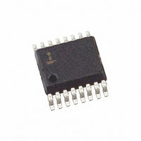
ISL6224CA Intersil, ISL6224CA Datasheet - Page 5

ISL6224CA
Manufacturer Part Number
ISL6224CA
Description
IC CONTROLLER PWM SINGLE 16-SSOP
Manufacturer
Intersil
Datasheet
1.ISL6224CAZ.pdf
(13 pages)
Specifications of ISL6224CA
Pwm Type
Current Mode
Number Of Outputs
1
Frequency - Max
690kHz
Duty Cycle
94%
Voltage - Supply
4 V ~ 24 V
Buck
Yes
Boost
No
Flyback
No
Inverting
No
Doubler
No
Divider
No
Cuk
No
Isolated
No
Operating Temperature
-10°C ~ 85°C
Package / Case
16-QSOP
Frequency-max
690kHz
Lead Free Status / RoHS Status
Contains lead / RoHS non-compliant
Available stocks
Company
Part Number
Manufacturer
Quantity
Price
Part Number:
ISL6224CA
Manufacturer:
INTERSIL
Quantity:
20 000
Part Number:
ISL6224CAZ
Manufacturer:
INTERSIL
Quantity:
20 000
Company:
Part Number:
ISL6224CAZ-T
Manufacturer:
INTERSIL
Quantity:
6 387
Functional Pin Description
VIN (Pin 1)
Provides battery voltage to the oscillator for feed-forward
rejection of the input voltage variation. Also, this pin
programs frequency of the internal clock and gain of the
ramp generator. When connected to the battery, which
voltage varies from 4V to 24V, the clock frequency is set to
300kHz and the ramp gain is set accordingly to
accommodate the wide input voltage range.
For two step conversion from the system 5V power rail, the
Vin pin is connected to ground via a 150kΩ resistor. This
arrangement changes the gain of the ramp generator to
accommodate the lower input voltage but does not change
the clock frequency.
When the Vin pin is connected to ground, the clock
frequency is set to 600kHz. The ramp generator gain is also
changed accordingly. This circuit arrangement enables the
designer to choose smaller output filter components.
PGOOD (Pin 2)
PGOOD is an open collector output used to indicate the
status of the output voltage. This pin is pulled high when the
system output is within ±10% of its respective nominal
voltage.
EN (Pin 3)
This pin provides the enable/disable function for the chip. The
IC is enabled when this pin is pulled over 2V or left open.
Note: a pulldown resistance of 100kΩ or less is required to
disable the controller.
OCSET (Pin 4)
A resistor from this pin to GND sets the overcurrent
protection threshold.
VOUT (Pin 5)
This pin is used for feedback of the output voltage to
properly position output voltage during operational mode
change.
VSEN (Pin 6)
This pin is connected to the output via a resistive divider and
provides the voltage feedback signal for the PWM controller.
The PGOOD, UVP, and OVP circuits use this signal to report
output voltage status.
SOFT (Pin 7)
This pin provides soft-start of the PWM controller. When the
EN pin is pulled high, the voltage on the capacitor connected
to the soft-start pin is rising linearly due to the 5
current. The output voltage follows the voltage on the
capacitor until it reaches the value of 0.9V. The further rise of
the voltage on the soft-start capacitor does not affect the
output voltage.
5
µA
pull-up
ISL6224
GND (Pin 8)
Signal ground for the IC.
PGND (Pin 9)
This is the power ground connection for PWM converter.
This pin is connected to the lower MOSFET’s source
terminal.
LGATE (Pin 10)
This pin provides the gate drive for the lower MOSFET.
VCC (Pin 11)
This pin provides power to the chip.
ISEN (Pin 12)
This pin is used to monitor the voltage drop across the lower
MOSFET for current feedback and overcurrent protection.
For precise current detection this input can be connected to
an optional current sense resistor placed in series with the
source of the lower MOSFET.
PHASE (Pin 13)
Connect this pin to the PHASE node of the converter. The
PHASE node is the junction point of the upper MOSFET
source, output filter inductor, and lower MOSFET drain.
UGATE (Pin 14)
This pin provides the gate drive for the upper MOSFET.
BOOT (Pin 15)
This pin powers the upper MOSFET drivers of the PWM
converter. Connect this pin to the junction of bootstrap
capacitor with the cathode of the bootstrap diode. Anode of
the bootstrap diode is connected to the VCC pin.
FCCM (Pin 16)
This pin, when pulled to VCC, restrains hysteretic operation
in light loads.
General Description
Operational Overview
The ISL6224 is a single-channel PWM controller intended
for chipset, DRAM, or other low voltage power needs of
modern notebook and sub-notebook PCs. The IC integrates
control circuits and feedback compensation for a single
synchronous buck converter. The output voltage is set in the
range of 0.9–5.5V by an external resistive divider.
The synchronous buck converter can be configured for
either 300kHz or 600kHz switching frequencies. When
operated from battery, a switching frequency of 300kHz is
recommended. When operating from 5V, switching
frequencies of 300kHz or 600kHz are an option. For 300kHz
operation, pin 1 should be connected through a resistor
(150K) to gnd. For 600kHz operation, pin 1 should simply be
June 8, 2006
FN9042.8


