PM6641TR STMicroelectronics, PM6641TR Datasheet - Page 35
PM6641TR
Manufacturer Part Number
PM6641TR
Description
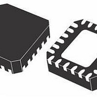
IC CTLR DDR2/3 MONO VR 48VFQFPN
Manufacturer
STMicroelectronics
Datasheet
1.PM6641TR.pdf
(47 pages)
Specifications of PM6641TR
Applications
Converter, DDR2, DDR3
Voltage - Input
2.7 ~ 5.5 V
Number Of Outputs
3
Voltage - Output
0.8 ~ 5.5 V
Operating Temperature
0°C ~ 85°C
Mounting Type
Surface Mount
Package / Case
48-VFQFN
For Use With
497-8425 - KIT EVAL PM6641 CHIPSET/DDR2/3
Lead Free Status / RoHS Status
Lead free / RoHS Compliant
Other names
497-6893-2
PM6641TR
PM6641TR
Available stocks
Company
Part Number
Manufacturer
Quantity
Price
Company:

Part Number:
PM6641TR
Manufacturer:
STM
Quantity:
35 839


PM6641
8
8.1
Components selection
The PM6641 switching regulator sections are buck converters employing a constant
frequency, current mode PWM current loop (see
page 24
The duty-cycle of the buck converter is, in steady-state conditions, given by
Equation 11
The switching frequency directly affects two parameters:
●
●
Inductor selection
Once the switching frequency has been defined, the inductance value depends on the
desired inductor current ripple. Low inductance value means great ripple current that brings
to poor efficiency and great output noise. On the other hand a great current ripple is
desirable for fast transient response when a load step is applied.
Otherwise, great inductance brings to good efficiency but the load transient response is
critical, especially if V
multiplied by the inductor ripple current must be taken in consideration; the PM6641
switching regulators current loop doesn’t need a minimum output ripple in order to work
properly, so a ceramic output capacitor can be considered a good choice.
A good trade-off between the transient response time, the efficiency, the cost and the size is
choosing the inductance value in order to maintain the inductor ripple current between 20%
and 50% (usually 30%) of the maximum output current.
The maximum inductor current ripple, ΔI
With these considerations, the inductance value can be calculated with the following
expression:
Equation 12
where f
ΔI
L
is the inductor current ripple.
Inductor size: greater frequencies mean smaller inductances. In notebook applications,
real estate solutions (i.e. low-profile power inductors) are mandatory also with high
saturation and root mean square (RMS) currents.
Efficiency: switching losses are proportional to the frequency. Generally, higher
frequencies imply lower efficiency.
SW
section for details).
is the switching frequency, V
INmin
- V
OUT
Doc ID 13510 Rev 3
is little. The product of the output capacitor’s ESR
L
=
IN
V
L,MAX
fsw
IN
D =
is the input voltage, V
−
Δ ⋅
V
V
, occurs at the maximum input voltage.
OUT
V
I
OUT
L
IN
Chapter 7.3: SW regulators control loop on
⋅
V
V
OUT
IN
OUT
is the output voltage and
Components selection
35/47
Related parts for PM6641TR
Image
Part Number
Description
Manufacturer
Datasheet
Request
R

Part Number:
Description:
IC MONO VR DDR2/3 PC VFQFPN-48
Manufacturer:
STMicroelectronics
Datasheet:

Part Number:
Description:
STMicroelectronics [RIPPLE-CARRY BINARY COUNTER/DIVIDERS]
Manufacturer:
STMicroelectronics
Datasheet:
Part Number:
Description:
STMicroelectronics [LIQUID-CRYSTAL DISPLAY DRIVERS]
Manufacturer:
STMicroelectronics
Datasheet:

Part Number:
Description:
BOARD EVAL FOR MEMS SENSORS
Manufacturer:
STMicroelectronics
Datasheet:
Part Number:
Description:
NPN TRANSISTOR POWER MODULE
Manufacturer:
STMicroelectronics
Datasheet:
Part Number:
Description:
TURBOSWITCH ULTRA-FAST HIGH VOLTAGE DIODE
Manufacturer:
STMicroelectronics
Datasheet:
Part Number:
Description:
Manufacturer:
STMicroelectronics
Datasheet:
Part Number:
Description:
DIODE / SCR MODULE
Manufacturer:
STMicroelectronics
Datasheet:
Part Number:
Description:
DIODE / SCR MODULE
Manufacturer:
STMicroelectronics
Datasheet:
Part Number:
Description:
Search -----> STE16N100
Manufacturer:
STMicroelectronics
Datasheet:
Part Number:
Description:
Search ---> STE53NA50
Manufacturer:
STMicroelectronics
Datasheet:
Part Number:
Description:
NPN Transistor Power Module
Manufacturer:
STMicroelectronics
Datasheet: