PM6641 STMicroelectronics, PM6641 Datasheet - Page 31

PM6641
Manufacturer Part Number
PM6641
Description
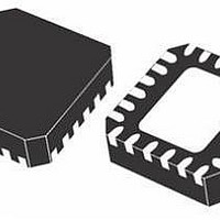
IC MONO VR DDR2/3 PC VFQFPN-48
Manufacturer
STMicroelectronics
Datasheet
1.PM6641TR.pdf
(47 pages)
Specifications of PM6641
Applications
Converter, DDR2, DDR3
Voltage - Input
2.7 ~ 5.5 V
Number Of Outputs
3
Voltage - Output
0.8 ~ 5.5 V
Operating Temperature
0°C ~ 85°C
Mounting Type
Surface Mount
Package / Case
48-VFQFN
Output Voltage
0.9 V
Output Current
3 A
Input Voltage
2.7 V to 5.5 V
Switching Frequency
1000 KHz
Operating Temperature Range
- 40 C to + 125 C
Mounting Style
SMD/SMT
For Use With
497-8425 - KIT EVAL PM6641 CHIPSET/DDR2/3
Lead Free Status / RoHS Status
Lead free / RoHS Compliant
Available stocks
Company
Part Number
Manufacturer
Quantity
Price
Company:
Part Number:
PM6641
Manufacturer:
BITECHNOL
Quantity:
2 000
Part Number:
PM6641
Manufacturer:
ST
Quantity:
20 000
Company:
Part Number:
PM6641TR
Manufacturer:
STM
Quantity:
35 839
PM6641
7.10
The synchronous mode of operation provides the following total input current:
Equation 8
whereas by shifting the three regulator turn on pulses of 120 deg the resulting total input
current is given by
Equation 9
that is
The PM6641 SET_PH1 pin, if tied to AVCC, enables the synchronous switching regulators
high side MOSFET turn on, whereas if tied to ground enables the 120 deg phase shifting.
Peak current limit
The peak current limit performed by the PM6641 switching regulators allows to monitor,
cycle by cycle, the inductor current; this feature prevents IC wire bonding overheating and
failure.
If the current sensed on the monolithic high side MOSFET reaches the programmed current
limit the regulator starts behaving like a current generator, more than a voltage regulator.
Consequently, if the output load still increases the rail output capacitor discharges itself and
the regulator works as current generator until the output under voltage occurs and the
regulator is latched off (see
details).
The pin 4 (CSNS) allows to select the right value for the peak current limit by inserting an
external resistor (R
RCSNS resistor or, when tied to AVCC, enables the internal reference (equal to a 50 kΩ
external resistor). A simple equation shows how to compute the right value for R
order to decrease the peak current limit:
Equation 10
3 ≅
. 1
73
I
CIN
,
times smaller than the one computed before.
I
DELAY
CSNS
CIN
,
SYNC
) between this pin and ground. CSNS forces a constant voltage on
=
=
Chapter 7.11.2: Output under voltage on page 33
T
SW
1
Doc ID 13510 Rev 3
T
SW
1
T
∫
SW
(
T
I
L
SW
∫
R
1
(
CSNS
I
+
L
1
I
L
+
2
I
+
L
=
2
I
L
α
+
3
⋅
I
)
L
2
V
3
I
dt
REF
CL
)
2
=
dt
=
T
SW
1
T
SW
1
(
I
2
+
( )
I 3
I
2
2
+
T
I
ON
2
Device description
)
T
ON
section for
CSNS
in
31/47


