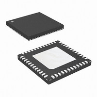
ISL6262CRZ-T Intersil, ISL6262CRZ-T Datasheet - Page 18

ISL6262CRZ-T
Manufacturer Part Number
ISL6262CRZ-T
Description
IC CORE REG 2PHASE 48-QFN
Manufacturer
Intersil
Datasheet
1.ISL6262CRZ.pdf
(27 pages)
Specifications of ISL6262CRZ-T
Applications
Converter, Intel IMVP-6
Voltage - Input
5 ~ 25 V
Number Of Outputs
1
Voltage - Output
0.3 ~ 1.5 V
Operating Temperature
-10°C ~ 100°C
Mounting Type
Surface Mount
Package / Case
48-VQFN
Lead Free Status / RoHS Status
Lead free / RoHS Compliant
Available stocks
Company
Part Number
Manufacturer
Quantity
Price
Overcurrent protection is tied to the voltage droop which is
determined by the resistors selected as described in the
“Component Selection and Application” section. After the
load-line is set, the OCSET resistor can be selected to
detect overcurrent at any level of droop voltage. An
overcurrent fault will occur when the load current exceeds
the overcurrent setpoint voltage while the regulator is in a
2-phase mode. While the regulator is in a 1-phase mode of
operation, the overcurrent setpoint is automatically reduced
by half. For overcurrents less than twice the OCSET level,
the over-load condition must exist for 120µs in order to trip
the OC fault latch. This is shown in Figure 24.
For over-loads exceeding twice the set level, the PWM
outputs will immediately shut off and PGOOD will go low to
maximize protection due to hard shorts.
In addition, excessive phase unbalance, for example, due to
gate driver failure, will be detected in two-phase operation
and the controller will be shut-down after one millisecond's
detection of the excessive phase current unbalance. The
phase unbalance is detected by the voltage on the ISEN
pins if the difference is greater than 7.5mV.
Undervoltage protection is independent of the overcurrent
limit. If the output voltage is less than the VID set value by
300mV or more, a fault will latch after one millisecond in that
condition. The PWM outputs will turn off and PGOOD will go
low. Note that most practical core regulators will have the
overcurrent set to trip before the -300mV undervoltage limit.
There are two levels of overvoltage protection and response.
For output voltage exceeding the set value by +200mV for
one millisecond, a fault is declared. All of the above faults
have the same action taken: PGOOD is latched low and the
upper and lower power FETs are turned off so that inductor
current will decay through the FET body diodes. This
condition can be reset by bringing VR_ON low or by bringing
VDD below 4V. When these inputs are returned to their high
operating levels, a soft-start will occur.
Refer to Figure 25, the second level of overvoltage
protection behaves differently. If the output exceeds 1.7V, an
OV fault is immediately declared, PGOOD is latched low and
the low-side FETs are turned on. The low-side FETs will
remain on until the output voltage is pulled down below
about 0.85V at which time all FETs are turned off. If the
output again rises above 1.7V, the protection process is
repeated. This offers the maximum amount of protection
against a shorted high-side FET while preventing output
ringing below ground. The 1.7V OV is not reset with VR_ON,
but requires that VDD be lowered to reset. The 1.7V OV
detector is active at all times that the controller is enabled
including after one of the other faults occurs so that the
processor is protected against high-side FET leakage while
the FETs are commanded off.
The ISL6262 has a thermal throttling feature. If the voltage
on the NTC pin goes below the 1.18V over-temperature
18
ISL6262
threshold, the VR_TT# pin is pulled low indicating the need
for thermal throttling to the system oversight processor. No
other action is taken within the ISL6262 in response to NTC
pin voltage.
Component Selection and Application
Soft-Start and Mode Change Slew Rates
The ISL6262 uses 2 slew rates for various modes of
operation. The first is a slow slew rate, used to reduce inrush
current during start-up. It is also used to reduce audible
noise when entering or exiting Deeper Sleep Mode. A faster
slew rate is used to exit out of Deeper Sleep and to enhance
system performance by achieving active mode regulation
more quickly. Note that the SOFT cap current is bidirectional.
The current is flowing into the SOFT capacitor when the
output voltage is commanded to rise, and out of the SOFT
capacitor when the output voltage is commanded to fall.
Refer to Figure 30. The two slew rates are determined by
commanding one of two current sources onto the SOFT pin.
As can be seen in Figure 30, the SOFT pin has a
capacitance to ground. Also, the SOFT pin is the input to the
error amplifier and is, therefore, the commanded system
voltage. Depending on the state of the system, i.e. Start-Up
or Active mode, and the state of the DPRSLPVR pin, one of
the two currents shown in Figure 30 will be used to charge or
discharge this capacitor, thereby controlling the slew rate of
the commanded voltage. These currents can be found under
the SOFT-START CURRENT section of the Electrical
Specification Table.
The first current, labelled I
Table as 41µA. This current is used during soft-start. The
second current, I
currents, labeled I
This total current is typically 200µA with a minimum of
175µA.
The IMVP-6 specification reveals the critical timing
associated with regulating the output voltage. The symbol,
FIGURE 30. SOFT PIN CURRENT SOURCES FOR FAST AND
C
SOFT
SLOW SLEW RATES
2
GV
sums with I
+
SOFT
in the Electrical Specification Table.
V
REF
I
SS
SS
, is given in the Specification
SS
to get the larger of the two
I
2
ISL6262
AMPLIFIER
+
ERROR
May 15, 2006
FN9199.2


