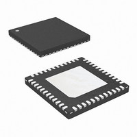
ISL6333BIRZ Intersil, ISL6333BIRZ Datasheet - Page 21

ISL6333BIRZ
Manufacturer Part Number
ISL6333BIRZ
Description
IC CTRLR PWM 3PHASE BUCK 48-QFN
Manufacturer
Intersil
Datasheet
1.ISL6333ACRZ.pdf
(40 pages)
Specifications of ISL6333BIRZ
Applications
Controller, Intel VR11
Voltage - Input
5 ~ 12 V
Number Of Outputs
1
Voltage - Output
0.5 ~ 1.6 V
Operating Temperature
-40°C ~ 85°C
Mounting Type
Surface Mount
Package / Case
48-VQFN
Lead Free Status / RoHS Status
Lead free / RoHS Compliant
Continuous Current Sensing
In order to realize proper current-balance, the currents in
each channel are sensed continuously every switching
cycle. During this time the current-sense amplifier uses the
ISEN inputs to reproduce a signal proportional to the
inductor current, I
scaled version of the inductor current.
The controllers support inductor DCR current sensing to
continuously sense each channel’s current for channel-current
balance. The internal circuitry, shown in Figure 6 represents
one channel of the controller. This circuitry is repeated for each
channel in the converter, but may not be active depending on
how many channels are operating.
Inductor windings have a characteristic distributed
resistance or DCR (Direct Current Resistance). For
simplicity, the inductor DCR is considered as a separate
lumped quantity, as shown in Figure 6. The channel current
I
Equation 4 shows the S-domain equivalent voltage, V
across the inductor.
A simple R-C network across the inductor (R
extracts the DCR voltage, as shown in Figure 6. The voltage
across the sense capacitor, V
proportional to the channel current I
If the R
time constant matches the inductor L/DCR time constant, then
V
L
V
V
C
, flowing through the inductor, passes through the DCR.
L
C
MOSFET
DRIVER
FIGURE 6. INDUCTOR DCR CURRENT SENSING
s ( )
is equal to the voltage drop across the DCR.
s ( )
=
1
SENSE
=
-C
I
---------------------------------------- - DCR I
(
I
L
n
s R
1
⋅
⎛
⎝
⋅
(
network components are selected such that their
-------------
DCR
s L
s L
CONFIGURATION
1
⋅
⋅
UGATE
LGATE
I
SEN
⋅
C
+
L
+
ISL6333 INTERNAL
1
. This sensed current, I
DCR
1
+
⎞
⎠
+
-
1
CIRCUIT
)
)
⋅
V
R
V
IN
C
ISEN
21
C
(s) -
⋅
, can be shown to be
L
R
INDUCTOR
L
1
ISL6333, ISL6333A, ISL6333B, ISL6333C
L
V
, shown in Equation 5.
RSET
ISEN-
ISEN+
L
I
(s)
L
V
R
C
DCR
SEN
SET
-
(s)
C
1
1
-
, is simply a
and C)
VCC
C
V
OUT
OUT
L
(EQ. 4)
(EQ. 5)
,
The capacitor voltage V
effective internal sense resistance, R
current through R
current. This current, I
then used by the controllers for load-line regulation,
channel-current balancing, and overcurrent detection and
limiting. Equation 6 shows that the proportion between the
channel-current, I
by the value of the effective sense resistance, R
the DCR of the inductor.
The effective internal R
current sensing process because it sets the gain of the load
line regulation loop as well as the gain of the channel-current
balance loop and the overcurrent trip level. The effective
internal R
through use of the R
from the R
internal R
The current sense circuitry operates in a very similar manner
for negative current feedback, where inductor current is
flowing from the output of the regulator to the PHASE node,
opposite of flow pictured in Figure 6. However, the range of
proper operation with negative current sensing is limited to
~60% of full positive current OCP threshold. Care should be
taken to avoid operation with negative current feedback
exceeding this threshold, as this may lead to momentary
loss of current balance between phases and disruption of
normal circuit operation.
Output Voltage Setting
The controllers use a digital to analog converter (DAC) to
generate a reference voltage based on the logic signals at
the VID pins. The DAC decodes the logic signals into one of
the discrete voltages shown in Table 2. Each VID pin is
pulled up to an internal 1.2V voltage by a weak current
source (40µA), which decreases to 0A as the voltage at the
VID pin varies from 0 to the internal 1.2V pull-up voltage.
External pull-up resistors or active-high output stages can
augment the pull-up current sources, up to a voltage of 5V.
R
I
VID7 VID6 VID5 VID4 VID3 VID2 VID1 VID0
SEN
ISEN
0
0
0
0
0
0
0
TABLE 2. VR11 VOLTAGE IDENTIFICATION CODES
=
=
I
L
0
0
0
0
0
0
0
--------- - R
400
ISEN
ISEN
⋅
SET
3
----------------- -
R
DCR
ISEN
⋅
resistance is user programmable and is set
resistance according to Equation 7.
pin to the VCC pin programs the effective
0
0
0
0
0
0
0
SET
ISEN
L
, and the sensed current, I
SET
0
0
0
0
0
0
0
SEN
which is proportional to the inductor
ISEN
C
pin. Placing a single resistor, R
, is then replicated across the
, is continuously sensed and is
0
0
0
0
0
0
0
resistance is important to the
0
0
0
0
1
1
1
ISEN
0
0
1
1
0
0
1
. This develops a
SEN
0
1
0
1
0
1
0
ISEN
, is driven
October 8, 2010
(EQ. 6)
1.60000
1.59375
1.58750
1.58125
1.57500
, and
VDAC
FN6520.3
(EQ. 7)
OFF
OFF
SET
,


