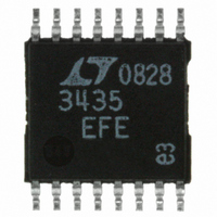
LT3435EFE#PBF Linear Technology, LT3435EFE#PBF Datasheet - Page 11

LT3435EFE#PBF
Manufacturer Part Number
LT3435EFE#PBF
Description
IC REG SW HV 3A 500KHZ 16-TSSOP
Manufacturer
Linear Technology
Type
Step-Down (Buck)r
Datasheet
1.LT3435EFEPBF.pdf
(24 pages)
Specifications of LT3435EFE#PBF
Internal Switch(s)
Yes
Synchronous Rectifier
No
Number Of Outputs
1
Voltage - Output
1.25 ~ 54 V
Current - Output
3A
Frequency - Switching
500kHz
Voltage - Input
3.3 ~ 60 V
Operating Temperature
-40°C ~ 125°C
Mounting Type
Surface Mount
Package / Case
16-TSSOP Exposed Pad, 16-eTSSOP, 16-HTSSOP
Primary Input Voltage
60V
No. Of Outputs
1
Output Voltage
68V
Output Current
2.4A
No. Of Pins
16
Operating Temperature Range
-40°C To +125°C
Msl
MSL 1 - Unlimited
Rohs Compliant
Yes
Lead Free Status / RoHS Status
Lead free / RoHS Compliant
Power - Output
-
Available stocks
Company
Part Number
Manufacturer
Quantity
Price
APPLICATIO S I FOR ATIO
taken to ensure the ripple and surge ratings are not
exceeded. The AVX TPS and Kemet T495 series are surge
rated AVX recommends derating capacitor operating volt-
age by 2:1 for high surge applications.
OUTPUT CAPACITOR
The output capacitor is normally chosen by its effective
series resistance (ESR) because this is what determines
output ripple voltage. To get low ESR takes volume, so
physically smaller capacitors have higher ESR. The ESR
range for typical LT3435 applications is 0.05Ω to 0.2Ω. A
typical output capacitor is an AVX type TPS, 100µF at 10V,
with a guaranteed ESR less than 0.1Ω. This is a “D” size
surface mount solid tantalum capacitor. TPS capacitors
are specially constructed and tested for low ESR, so they
give the lowest ESR for a given volume. The value in
microfarads is not particularly critical and values from
22µF to greater than 500µF work well, but you cannot
cheat Mother Nature on ESR. If you find a tiny 22µF solid
tantalum capacitor, it will have high ESR and output ripple
voltage could be unacceptable. Table 2 shows some
typical solid tantalum surface mount capacitors.
Table 2. Surface Mount Solid Tantalum Capacitor ESR
and Ripple Current
E CASE SIZE
AVX TPS
D CASE SIZE
AVX TPS
C CASE SIZE
AVX TPS
Many engineers have heard that solid tantalum capacitors
are prone to failure if they undergo high surge currents.
This is historically true and type TPS capacitors are
specially tested for surge capability but surge ruggedness
is not a critical issue with the output capacitor. Solid
tantalum capacitors fail during very high turn-on surges
which do not occur at the output of regulators. High
discharge surges, such as when the regulator output is
dead shorted, do not harm the capacitors.
ESR MAX (Ω)
U
0.1 to 0.3
0.1 to 0.3
0.2
U
W
RIPPLE CURRENT (A)
0.7 to 1.1
0.7 to 1.1
0.5
U
Unlike the input capacitor RMS, ripple current in the
output capacitor is normally low enough that ripple cur-
rent rating is not an issue. The current waveform is
triangular with a typical value of 200mA
to calculate this is:
CERAMIC CAPACITORS
Higher value, lower cost ceramic capacitors are now
becoming available. They are generally chosen for their
good high frequency operation, small size and very low
ESR (effective series resistance). Low ESR reduces output
ripple voltage but also removes a useful zero in the loop
frequency response, common to tantalum capacitors. To
compensate for this a resistor R
with the V
must be taken however since this resistor sets the high
frequency gain of the error amplifier including the gain at
the switching frequency. If the gain of the error amplifier
is high enough at the switching frequency output ripple
voltage (although smaller for a ceramic output capacitor)
may still affect the proper operation of the regulator. A
filter capacitor C
with a small feedforward capacitor C
control possible ripple at the V
OUTPUT RIPPLE VOLTAGE
Figure 3 shows a typical output ripple voltage waveform
for the LT3435. Ripple voltage is determined by the
impedance of the output capacitor and ripple current
through the inductor. Peak-to-peak ripple current through
the inductor into the output capacitor is:
Output capacitor ripple current (RMS)
I
I
RIPPLE RMS
P-P
=
V
(
C
OUT
compensation capacitor C
( )( )( )
V
)
(
IN
V
=
F
IN
in parallel with the R
0 29
L f
–
.
V
OUT
( )(
V
( )( )( )
OUT
L f V
)
C
V
IN
C
pin.
IN
can be placed in series
–
V
C
FB
OUT
C
/C
RMS
, is suggested to
(Figure 10). Care
C
)
network, along
LT3435
. The formula
=
I
P-P
12
11
3435fa


