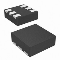
ISL9103IRUNZ-T Intersil, ISL9103IRUNZ-T Datasheet - Page 9

ISL9103IRUNZ-T
Manufacturer Part Number
ISL9103IRUNZ-T
Description
IC CONV SYNC 3.3V 500MA 6-UTDFN
Manufacturer
Intersil
Type
Step-Down (Buck)r
Datasheet
1.ISL9103AIRUAZ-T.pdf
(13 pages)
Specifications of ISL9103IRUNZ-T
Internal Switch(s)
Yes
Synchronous Rectifier
Yes
Number Of Outputs
1
Voltage - Output
3.3V
Current - Output
500mA
Frequency - Switching
2.4MHz
Voltage - Input
2.7 ~ 6 V
Operating Temperature
-40°C ~ 85°C
Mounting Type
Surface Mount
Package / Case
6-µTDFN
Lead Free Status / RoHS Status
Lead free / RoHS Compliant
Power - Output
-
Block Diagram
Theory of Operation
The ISL9103, ISL9103A is a step-down switching regulator
optimized for battery-powered handheld applications. The
regulator operates at typical 2.4MHz fixed switching
frequency under heavy load condition to allow small external
inductor and capacitors to be used for minimal printed-circuit
board (PCB) area. At light load, the regulator can
automatically enter the skip mode (PFM mode) to reduce the
switching frequency to minimize the switching loss and to
maximize the battery life. The quiescent current under skip
mode, and under no load and no switch condition is typically
only 20µA. The supply current is typically only 0.05µA when
the regulator is disabled.
PWM Control Scheme
The ISL9103, ISL9103A uses the peak-current-mode
pulse-width modulation (PWM) control scheme for fast
transient response and pulse-by-pulse current limiting.
Figure 22 shows the circuit functional block diagram. The
current loop consists of the oscillator, the PWM comparator
COMP, current sensing circuit, and the slope compensation
for the current loop stability. The current sensing circuit
consists of the resistance of the P-Channel MOSFET when it
is turned on and the Current Sense Amplifier (CSA). The
NOTE: For Adjustable output version, the internal feedback resistor divider is disabled and the FB pin
is directly connected to the error amplifier.
F B
E N
S H U T D O W N
*N O T E : F O R F IX E D O U T P U T O P T IO N S O N L Y
*N O T E
B A N D G A P
9
V R E F 3
S T A R T
S O F T -
V R E F
S T A
S O
S L O P E
F T
R T
C O M P
+
+
FIGURE 22. FUNCTIONAL BLOCK DIAGRAM
E A M P
S C P
ISL9103, ISL9103A
X
+
C O M P
O S C IL L A T O R
control reference for the current loops comes from the Error
Amplifier (EAMP) of the voltage loop.
The PWM operation is initialized by the clock from the
oscillator. The P-Channel MOSFET is turned on at the
beginning of a PWM cycle and the current in the P-Channel
MOSFET starts ramping up. When the sum of the CSA
output and the compensation slope reaches the control
reference of the current loop, the PWM comparator COMP
sends a signal to the PWM logic to turn off the P-Channel
MOSFET and to turn on the N-Channel MOSFET. The
N-MOSFET remains on till the end of the PWM cycle. Figure 23
shows the typical operating waveforms during the normal PWM
operation. The dotted lines illustrate the sum of the slope
compensation ramp and the CSA output.
S K IP
O C P
B L E E D IN G
+
+
F E T
C O N T R O L L E R
S H U T D O W N
V R E F 1
P R O T E C T IO N
V R E F 2
P W M /P F M
L O G IC
D R IV E R
Z E R O -C R O S S
S E N S IN G
1 0 0 Ω
C S A
+
S W
V IN
G N D
November 24, 2009
FN6828.2


