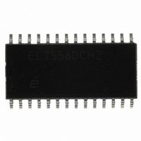
EL7556DCMZ Intersil, EL7556DCMZ Datasheet - Page 11

EL7556DCMZ
Manufacturer Part Number
EL7556DCMZ
Description
IC REG 6A DC/DC SW SD 28SOIC
Manufacturer
Intersil
Type
Step-Down (Buck)r
Datasheet
1.EL7556DCMZ.pdf
(11 pages)
Specifications of EL7556DCMZ
Internal Switch(s)
Yes
Synchronous Rectifier
Yes
Number Of Outputs
1
Voltage - Output
1 ~ 3.8 V
Current - Output
6A
Frequency - Switching
1MHz
Voltage - Input
5V
Operating Temperature
-40°C ~ 85°C
Mounting Type
Surface Mount
Package / Case
28-SOIC (7.5mm Width)
Power - Output
21W
Lead Free Status / RoHS Status
Lead free / RoHS Compliant
Available stocks
Company
Part Number
Manufacturer
Quantity
Price
maintain a constant gain ratio. The recommended ratio of
C
Temperature Sensor
An internal temperature sensor continuously monitors die
temperature. In the event that die temperature exceeds the
thermal trip-point, the OT pin will output a logic 0. The upper
and lower trip points are set to 135°C and 100°C,
respectively. To enable thermal shutdown this pin should be
tied directly to OUTEN. Use of this feature is recommended
during normal operation
Power Good and Power On Reset
During power up the output regulator will be disabled until
V
500mV of hysteresis is present to eliminate noise induced
oscillations.
Under-voltage and over-voltage conditions on the regulator
output are detected through an internal window comparator.
A logic 1 on the PWRGD output indicates that regulated
output voltage is within ±10% of the nominally programmed
output voltage. Although small, the typical values of the
PWRGD threshold will vary with changes to external
feedback (and resultant loop gain) of the system. This
dependence is shown in the typical performance curves.
Thermal Management
The EL7556D utilizes “fused lead” packaging technology in
conjunction with the system board layout to achieve a lower
thermal resistance than typically found in standard 28-pin
SO packages. By fusing (or connecting) multiple external
leads to the die substrate within the package, a very
conductive heat path to the outside of the package is
created. This conductive heat path MUST then be connected
to a heat sinking area on the PCB in order to dissipate heat
out and away from the device. The conductive paths for the
EL7556D package are the fused leads: # 7, 9, 10, 11, 12, 18,
and 19. If a sufficient amount of PCB metal area is
connected to the fused package leads, a junction-to-ambient
thermal resistance of approximately 31°C/W can be
achieved (compared to 78°C/W for a standard SO28
package). The general relationship between PCB heat-
sinking metal area and the thermal resistance for this
package is shown in the Performance Curves section of this
data sheet. It can be readily seen that the thermal resistance
for this package approaches an asymptotic value of
approximately 31°C/W without any airflow.
Intersil products are sold by description only. Intersil Corporation reserves the right to make changes in circuit design, software and/or specifications at any time without
notice. Accordingly, the reader is cautioned to verify that data sheets are current before placing orders. Information furnished by Intersil is believed to be accurate and
reliable. However, no responsibility is assumed by Intersil or its subsidiaries for its use; nor for any infringements of patents or other rights of third parties which may result
from its use. No license is granted by implication or otherwise under any patent or patent rights of Intersil or its subsidiaries.
OSC
IN
reaches a value of approximately 4.0V. Approximately
to C
SLOPE
All Intersil U.S. products are manufactured, assembled and tested utilizing ISO9000 quality systems.
is 1.5:1
Intersil Corporation’s quality certifications can be viewed at www.intersil.com/design/quality
For information regarding Intersil Corporation and its products, see www.intersil.com
11
EL7556D
Additional information can be found in Application Note #8
(Measuring the Thermal Resistance of Power Surface-
Mount Packages).
If the thermal shutdown pin is connected to OUTEN the IC
will enter thermal shutdown when the maximum junction
temperature is reached. For a thermal shutdown of 135ºC
and power dissipation of 2.2W the ambient temperature is
limited to a maximum value of 67ºC (typical). The ambient
temperature range can be extended with the application of
air flow. For example, the addition of 100LFM reduces the
thermal resistance by approximately 15% and can extend
the operating ambient to 77ºC (typical). Since the thermal
performance of the IC is heavily dependent on the board
layout, the system designer should exercise care during the
design phase to ensure that the IC will operate under the
worst-case environmental conditions.


