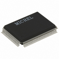
KS8993M Micrel Inc, KS8993M Datasheet - Page 10

KS8993M
Manufacturer Part Number
KS8993M
Description
IC SWITCH 10/100 3PORT 128PQFP
Manufacturer
Micrel Inc
Specifications of KS8993M
Applications
*
Mounting Type
Surface Mount
Package / Case
128-MQFP, 128-PQFP
Number Of Primary Switch Ports
3
Internal Memory Buffer Size
32
Operating Supply Voltage (typ)
1.8/2.5/3.3V
Fiber Support
Yes
Integrated Led Drivers
Yes
Phy/transceiver Interface
MII/SNI
Power Supply Type
Analog/Digital
Package Type
PQFP
Data Rate (typ)
10/100Mbps
Vlan Support
Yes
Operating Temperature (max)
70C
Operating Temperature (min)
0C
Pin Count
128
Mounting
Surface Mount
Jtag Support
No
Operating Supply Voltage (max)
1.89/3.465V
Operating Supply Voltage (min)
1.71/3.135V
Power Dissipation
800mW
Supply Current
0.1/0.19A
Operating Temperature Classification
Commercial
Data Rate
100Mbps
Lead Free Status / RoHS Status
Lead free / RoHS Compliant
For Use With
576-1013 - BOARD EVAL EXPERIMENT KS8993M
Lead Free Status / RoHS Status
Not Compliant, Lead free / RoHS Compliant
Available stocks
Company
Part Number
Manufacturer
Quantity
Price
Part Number:
KS8993M
Manufacturer:
MICREL/麦瑞
Quantity:
20 000
Micrel, Inc.
April 2005
Note:
1. P = Power supply.
Pin Number
8
9
10
11
12
13
14
15
16
17
18
19
20
21
22
23
24
25
Opu = Output with internal pull-up.
Gnd = Ground.
O = Output.
Ipu = Input w/ internal pull-up.
Ipd = Input w/ internal pull-down.
Pin Name
VDDIO
NC
NC
NC
ADVFC
P2ANEN
P2SPD
P2DPX
P2FFC
NC
NC
NC
P2LED3
DGND
VDDC/VOUT_1
V8
LEDSEL1
NC
P1LED3
Type
P
Ipd
Ipd
Ipu
Ipu
Ipu
Ipd
Ipd
Ipd
Opu
Ipd
Ipd
Opd
Gnd
P
Ipd
O
Opd
(1)
Opd = Output internal pull-down.
10
Description
3.3V digital V
No connect
No connect
No connect
1 = advertise the switch’s flow control capability via auto
negotiation.
0 = will not advertise the switch’s flow control capability via
auto negotiation.
1 = enable auto negotiation on port 2
0 = disable auto negotiation on port 2
1 = force port 2 to 100BT if P2ANEN = 0
0 = force port 2 to 10BT if P2ANEN = 0
1 = port 2 default to full duplex mode if P2ANEN = 1 and auto
negotiation fails. Force port 2 in full duplex mode if P2ANEN
= 0.
0 = port 2 default to half duplex mode if P2ANEN = 1 and
auto negotiation fails. Force port 2 in half duplex mode if
P2ANEN = 0.
1 = always enable (force) port 2 flow control feature
0 = port 2 flow control feature enable is determined by auto
negotiation result.
No connect
No connect
No connect
Port 2 LED indicator
Note: Internal pull-down is weak; it will not turn ON the LED.
See description in pin 4.
Digital ground
V
digital core V
V
supply the KS8993ML’s input power pins: V
V
LED display mode select
See description in pins 1 and 4.
No connect
Port 1 LED indicator
Note: An external 1K pull-down is needed on this pin if it is
connected to a LED. The 1K resistor will not turn ON the
LED.
See description in pin 1.
DDC
OUT_1V8
DDC
: For KS8993M, this is an input power pin for the 1.8V
(pins 91 and 123), and V
: For KS8993ML, this is a 1.8V output power pin to
DD
DD
.
DDA
(pins 38, 43, and 57).
KS8993M/ML/MI
DDAP
M9999-041205
(pin 63),


