STM8/128-MCKIT STMicroelectronics, STM8/128-MCKIT Datasheet - Page 11
STM8/128-MCKIT
Manufacturer Part Number
STM8/128-MCKIT
Description
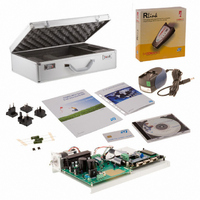
EVAL KIT MOTOR CONTROL STM8S
Manufacturer
STMicroelectronics
Series
STM8Sr
Datasheets
1.STM8128-MCKIT.pdf
(22 pages)
2.STM8128-MCKIT.pdf
(4 pages)
3.STM8128-MCKIT.pdf
(41 pages)
Specifications of STM8/128-MCKIT
Main Purpose
Power Management, Motor Control
Embedded
Yes, MCU, 8-Bit
Utilized Ic / Part
STM8S2xx
Primary Attributes
Brushless DC (BLDC) & AC Induction (ACIM) Motors
Secondary Attributes
Joystick & LCD User Interface
Processor To Be Evaluated
STM8S
Data Bus Width
8 bit
Operating Supply Voltage
2.95 V to 5.5 V
Silicon Manufacturer
ST Micro
Silicon Core Number
STM8
Features
Motor Control Applications, The Inverter Is Driven Using The Space Vector PWM Modulation Technique
Lead Free Status / RoHS Status
Not applicable / Not applicable
Other names
497-10032


UM0709
3.5
Caution:
Table 3.
Hardware configuration for an AC induction motor
This section describes the procedure for operating the STM8/128-MCKIT with an AC
induction motor. You must change the default settings that are present on the STM8
evaluation board and on the power board when you receive the STM8/128-MCKIT starter kit
because they are intended for a PMSM motor. When you are running the AC induction
motor, follow these steps:
1.
2.
3.
4.
5.
6.
7.
8.
9.
After re-programming the STM8S microcontroller with the ACIM motor control firmware, the
STM8/128-EVAL is now ready to run with your AC induction motor.
Before supplying the board, double check proper connections, make sure that there are no
metal parts on, below or around the PCB and that there are no undesired earth/ground
loops due to measuring equipment such as an oscilloscope.
Jumper
J13
J1
J2
J3
J4
J5
Remove the BLDC daughterboard (MB843) from the STM8/128-EVAL evaluation board
(MB631).
Remove the adapter board (MB844) from the power board (MB459B).
Change the jumpers on the power board (MB459B) to the settings required for running
with an AC induction motor. Refer to
an AC induction motor
MB459B power board user manual for the location of the jumpers on the board.
If the peak value of the motor phase current should be greater than 3 ampere, replace
the R4 shunt resistor on the power board (MB459B) by the 0.1 ohm resistor included in
the bag delivered with the kit.
Verify that the jumpers on the STM8/128-EVAL evaluation board (MB631) are in their
default position. Refer to
motor
board user manual for the location of jumpers on the board.
Disconnect the PMSM motor from the power board's MOTOR connectors (J5 and J8).
The power board (MB459B), the STM8/128-EVAL evaluation board (MB631), and the
provided PMSM motor are already assembled together over a metal support when you
receive the kit.
Connect your AC induction motor to the power board by connecting the three phases to
the J5 connector, and the tachometer cables to the J6 connector.
Power up STM8/128-EVAL evaluation board with auxiliary power supply block TR30R.
Power up the power board by connecting the output terminals of your DC power supply
to the MAINS connector (J3). The provided voltage must not be higher than 42 V DC or
32 Veff AC (GND recommended).
for information on jumper settings, and if necessary, to the STM8/128-EVAL
BLDC daughterboard MB843 jumper settings for a BLDC motor (default)
Present and set on default position of silk-screen printing (SENSORLESS)
Present and set on default position of silk-screen printing (VARIABLE)
Present and set on default position of silk-screen printing
Present and set on default position of silk-screen printing
Present and set on default position of silk-screen printing
Present and set on default position of silk-screen printing
for information on jumper settings, and if necessary, to the
Table 5: STM8 eval board jumper settings for an AC induction
Doc ID 15774 Rev 2
Table 4: MB459B power board jumper settings for
Setting
STM8/128-MCKIT hardware setup
11/22
Related parts for STM8/128-MCKIT
Image
Part Number
Description
Manufacturer
Datasheet
Request
R

Part Number:
Description:
KIT STARTER FOR STM8S207/8 SER
Manufacturer:
STMicroelectronics
Datasheet:

Part Number:
Description:
BOARD DAUGHTER FOR STM8S207/8
Manufacturer:
STMicroelectronics
Datasheet:

Part Number:
Description:
EVAL KIT TOUCH SENSING STM8S
Manufacturer:
STMicroelectronics
Datasheet:

Part Number:
Description:
BOARD EVAL FOR STM8S
Manufacturer:
STMicroelectronics
Datasheet:
Part Number:
Description:
STM8 Series 8-bit 8 KB Flash 1 KB RAM 16 MHz Microcontroller - TSSOP-20
Manufacturer:
STMicroelectronics
Datasheet:
Part Number:
Description:
STMicroelectronics [RIPPLE-CARRY BINARY COUNTER/DIVIDERS]
Manufacturer:
STMicroelectronics
Datasheet:
Part Number:
Description:
STMicroelectronics [LIQUID-CRYSTAL DISPLAY DRIVERS]
Manufacturer:
STMicroelectronics
Datasheet:

Part Number:
Description:
BOARD EVAL FOR MEMS SENSORS
Manufacturer:
STMicroelectronics
Datasheet:
Part Number:
Description:
NPN TRANSISTOR POWER MODULE
Manufacturer:
STMicroelectronics
Datasheet:
Part Number:
Description:
TURBOSWITCH ULTRA-FAST HIGH VOLTAGE DIODE
Manufacturer:
STMicroelectronics
Datasheet:
Part Number:
Description:
Manufacturer:
STMicroelectronics
Datasheet:
Part Number:
Description:
DIODE / SCR MODULE
Manufacturer:
STMicroelectronics
Datasheet: