STM8/128-MCKIT STMicroelectronics, STM8/128-MCKIT Datasheet - Page 7
STM8/128-MCKIT
Manufacturer Part Number
STM8/128-MCKIT
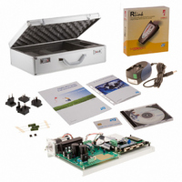
Description
EVAL KIT MOTOR CONTROL STM8S
Manufacturer
STMicroelectronics
Series
STM8Sr
Datasheets
1.STM8128-MCKIT.pdf
(22 pages)
2.STM8128-MCKIT.pdf
(4 pages)
3.STM8128-MCKIT.pdf
(41 pages)
Specifications of STM8/128-MCKIT
Main Purpose
Power Management, Motor Control
Embedded
Yes, MCU, 8-Bit
Utilized Ic / Part
STM8S2xx
Primary Attributes
Brushless DC (BLDC) & AC Induction (ACIM) Motors
Secondary Attributes
Joystick & LCD User Interface
Processor To Be Evaluated
STM8S
Data Bus Width
8 bit
Operating Supply Voltage
2.95 V to 5.5 V
Silicon Manufacturer
ST Micro
Silicon Core Number
STM8
Features
Motor Control Applications, The Inverter Is Driven Using The Space Vector PWM Modulation Technique
Lead Free Status / RoHS Status
Not applicable / Not applicable
Other names
497-10032


UM0709
3.2
3.3
Brushless DC motor (default)
The brushless DC motor (BLDC) is a rotating electric machine where the stator is a classic
3-phase stator like that of an induction motor and the rotor has surface-mounted permanent
magnets. In this respect, the BLDC motor is equivalent to an induction motor where the air
gap magnetic field is produced by a permanent magnet. The use of a permanent magnet to
generate a substantial air gap magnetic flux makes it possible to design highly efficient
motors.
A BLDC motor is driven by trapezoidal currents coupled with the given rotor position. The
generated stator flux together with the rotor flux, which is generated by a rotor magnet,
defines the torque, and thus speed, of the motor. The trapezoidal currents have to be
applied to the 3-phase winding system in a way that angle between the stator flux and the
rotor flux is kept close to 90° to get the maximum generated torque. To meet this criterion,
the motor requires electronic control for proper operation.
For a common 3-phase BLDC motor, a standard 3-phase power stage is used.
The same power stage is used for AC induction and BLDC motors. The power stage utilizes
six power transistors with independent switching. The power transistors are switched in the
also called six step operation.
AC induction motor
The AC induction motor is a rotating electric machine designed to operate from a 3-phase
source of alternating voltage.
The stator is a classic 3-phase stator with the winding displaced by 120°.
The most common type of induction motor has a squirrel cage rotor in which aluminum
conductors or bars are shorted together at both ends of the rotor by cast aluminum end
rings. When three currents flow through the three symmetrically placed windings, a
sinusoidally distributed air gap flux generating the rotor current is produced. The interaction
of the sinusoidally distributed air gap flux and induced rotor currents produces a torque on
the rotor. The mechanical angular velocity of the rotor is lower then the angular velocity of
the flux wave by so called slip velocity.
In adjustable speed applications, AC induction motors are powered by inverters. The
inverter converts DC power to AC power at the required frequency and amplitude.
The inverter consists of three half-bridge units where the upper and lower switches are
controlled complementarily. As the power device's turn-off time is longer than its turn-on
time, some dead-time must be inserted between the turn-off of one transistor of the half
bridge and turn-on of its complementary device.
The output voltage is mostly created by a pulse width modulation (PWM) technique. The 3-
phase voltage waves are shifted 120° to each other and thus a 3-phase motor can be
supplied.
Doc ID 15774 Rev 2
STM8/128-MCKIT hardware setup
7/22
Related parts for STM8/128-MCKIT
Image
Part Number
Description
Manufacturer
Datasheet
Request
R

Part Number:
Description:
KIT STARTER FOR STM8S207/8 SER
Manufacturer:
STMicroelectronics
Datasheet:

Part Number:
Description:
BOARD DAUGHTER FOR STM8S207/8
Manufacturer:
STMicroelectronics
Datasheet:

Part Number:
Description:
EVAL KIT TOUCH SENSING STM8S
Manufacturer:
STMicroelectronics
Datasheet:

Part Number:
Description:
BOARD EVAL FOR STM8S
Manufacturer:
STMicroelectronics
Datasheet:
Part Number:
Description:
STM8 Series 8-bit 8 KB Flash 1 KB RAM 16 MHz Microcontroller - TSSOP-20
Manufacturer:
STMicroelectronics
Datasheet:
Part Number:
Description:
STMicroelectronics [RIPPLE-CARRY BINARY COUNTER/DIVIDERS]
Manufacturer:
STMicroelectronics
Datasheet:
Part Number:
Description:
STMicroelectronics [LIQUID-CRYSTAL DISPLAY DRIVERS]
Manufacturer:
STMicroelectronics
Datasheet:

Part Number:
Description:
BOARD EVAL FOR MEMS SENSORS
Manufacturer:
STMicroelectronics
Datasheet:
Part Number:
Description:
NPN TRANSISTOR POWER MODULE
Manufacturer:
STMicroelectronics
Datasheet:
Part Number:
Description:
TURBOSWITCH ULTRA-FAST HIGH VOLTAGE DIODE
Manufacturer:
STMicroelectronics
Datasheet:
Part Number:
Description:
Manufacturer:
STMicroelectronics
Datasheet:
Part Number:
Description:
DIODE / SCR MODULE
Manufacturer:
STMicroelectronics
Datasheet: