ATA6823-DK Atmel, ATA6823-DK Datasheet - Page 10
ATA6823-DK
Manufacturer Part Number
ATA6823-DK
Description
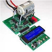
BOARD EVALUATION FOR ATA6823
Manufacturer
Atmel
Type
PWM Controllersr
Specifications of ATA6823-DK
Main Purpose
Power Management, Motor Control
Embedded
No
Utilized Ic / Part
ATA6823
Primary Attributes
Brush DC Motors, 8 ~ 18V, LIN Interface, Watchdog, 5V Regulator
Secondary Attributes
Cross Conduction, Under/Over Voltage, Short Circuit, & Temperature Protection
Input Voltage
8 V to 18 V
Product
Power Management Modules
Lead Free Status / RoHS Status
Contains lead / RoHS non-compliant
For Use With/related Products
ATA6823


3.6
3.6.1
Figure 3-5.
10
LIN Transceiver
Atmel ATA6823
Transmit Mode
(input to transmitting Node)
(output of receiving Node 1)
(output of receiving Node 2)
TX
RX
RX
V
(Transceiver
supply
of transmitting
node)
S
Definition of Bus Timing Parameters
TH
TH
TH
TH
Rec(max)
Dom(max)
Rec(min)
Dom(min)
A bi-directional bus interface is implemented for data transfer between the LIN bus and the
local LIN protocol controller.
The transceiver consists of a low side driver (1.2V at 40mA) with slew rate control, wave shap-
ing, current limitation, and a high-voltage comparator followed by a debouncing unit in the
receiver.
During transmission, the data at the pin TX will be transferred to the bus driver to generate a
bus signal on pin LIN.
To minimize the electromagnetic emission of the bus line, the bus driver has an integrated
slew rate control and wave-shaping unit. Transmission will be interrupted in the following
cases:
• Thermal shutdown active or overtemperature LIN active
• Sleep mode
t
Bit
t
rx_pdf(1)
LIN Bus Signal
t
t
Bus_dom(min)
Bus_dom(max)
t
Bit
t
rx_pdr(2)
t
Bus_rec(min)
t
Bus_rec(max)
t
rx_pdr(1)
t
Bit
Thresholds of
receiving node 1
Thresholds of
receiving node 2
t
rx_pdf(2)
4856K–AUTO–01/11
Related parts for ATA6823-DK
Image
Part Number
Description
Manufacturer
Datasheet
Request
R

Part Number:
Description:
IC H-BRIDGE MOTOR DRIVER 32-QFN
Manufacturer:
Atmel
Datasheet:

Part Number:
Description:
Motor / Motion / Ignition Controllers & Drivers Gate Driver IC
Manufacturer:
Atmel
Datasheet:

Part Number:
Description:
H-bridge Motor Driver
Manufacturer:
ATMEL Corporation
Datasheet:

Part Number:
Description:
DEV KIT FOR AVR/AVR32
Manufacturer:
Atmel
Datasheet:
Part Number:
Description:
INTERVAL AND WIPE/WASH WIPER CONTROL IC WITH DELAY
Manufacturer:
ATMEL Corporation
Datasheet:
Part Number:
Description:
Low-Voltage Voice-Switched IC for Hands-Free Operation
Manufacturer:
ATMEL Corporation
Datasheet:
Part Number:
Description:
MONOLITHIC INTEGRATED FEATUREPHONE CIRCUIT
Manufacturer:
ATMEL Corporation
Datasheet:
Part Number:
Description:
AM-FM Receiver IC U4255BM-M
Manufacturer:
ATMEL Corporation
Datasheet:
Part Number:
Description:
Monolithic Integrated Feature Phone Circuit
Manufacturer:
ATMEL Corporation
Datasheet:
Part Number:
Description:
Multistandard Video-IF and Quasi Parallel Sound Processing
Manufacturer:
ATMEL Corporation
Datasheet:
Part Number:
Description:
High-performance EE PLD
Manufacturer:
ATMEL Corporation
Datasheet:
Part Number:
Description:
8-bit Flash Microcontroller
Manufacturer:
ATMEL Corporation
Datasheet: