ATA6823-DK Atmel, ATA6823-DK Datasheet - Page 23
ATA6823-DK
Manufacturer Part Number
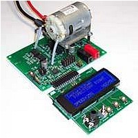
ATA6823-DK
Description
BOARD EVALUATION FOR ATA6823
Manufacturer
Atmel
Type
PWM Controllersr
Specifications of ATA6823-DK
Main Purpose
Power Management, Motor Control
Embedded
No
Utilized Ic / Part
ATA6823
Primary Attributes
Brush DC Motors, 8 ~ 18V, LIN Interface, Watchdog, 5V Regulator
Secondary Attributes
Cross Conduction, Under/Over Voltage, Short Circuit, & Temperature Protection
Input Voltage
8 V to 18 V
Product
Power Management Modules
Lead Free Status / RoHS Status
Contains lead / RoHS non-compliant
For Use With/related Products
ATA6823


8. Electrical Characteristics (Continued)
All parameters given are valid for V
4856K–AUTO–01/11
* Type: A = 100% tested, B = 100% correlation tested, C = Characterized on samples, D = Design parameter
Notes:
7.10
7.11
7.12
7.13
7.15
7.16
7.17 Fall time low-side driver
7.18 Rise time low-side driver
7.19
7.20
7.21 Fall time high-side driver
7.22 Rise time high-side driver
7.23 Cross conduction time
7.24 External resistor
No. Parameters
7.9
Output peak current at pins
Hx, switched to LOW
Output peak current at pins
Hx, switched to HIGH
Static switch output low
voltage at pins Hx and Lx
Static high-side switch
output high-voltage pins
H1, H2
Sink resistance between
Hx and Sx
Dynamic Parameters
Propagation delay time,
low-side driver from high to
low
Propagation delay time,
low-side driver from low to
high
Propagation delay time,
high-side driver from high
to low
Propagation delay time,
high-side driver from low to
high
1. EN, DIR, PWM = high
2. The use of X7R material is recommended
3. For higher values, stability at zero load is not guaranteed
4. Tested during qualification only
5. Value depends on T
6. Tested during characterization only
7. Supplied by charge pump
8. See section
9. Voltage between source-drain of external switching transistors in active case
10. The short-circuit message will never be generated for switch-on time < t
“Cross Conduction Time”
OSC
THUV
Test Conditions
V
V
V
V
V
V
V
I
I
I
(PWM = static)
V
I_VG = –20mA
Figure 3-6 on page 13
V
V
V
C
V
Figure 3-6 on page 13
V
V
V
C
V
R
Hx
Lx
Lx
; function tested with digital test pattern
VBAT
Sx
Hx
VBAT
Sx
Hx
Sx
VBAT
VBAT
VBAT
VBAT
VBAT
VBAT
VBAT
VBAT
VBAT
Gx
Gx
CC
= 1mA
= 1mA
= –10µA
= V
= V
= V
= V
= 0V
= 5nF
= 5nF
= 10k , C
V
= 13.5V
= 13.5V
= 13.5V
= 13.5V
= 13.5V
= 13.5V,
= V
= 13.5V
= 13.5V
= 13.5V
= 13.5V
VBAT
VBAT
VBAT
VBAT
VBAT
PBAT
+ 3V
+ 3V
V
= 9V,
CC
THOV
= 1nF
and for –40°C
(8)
18, 20,
17, 18,
18, 20
18, 20
26, 27
18, 20
19, 20
26, 27
26, 27
26, 27
26, 27
18, 20
18, 20
18, 20
18, 20
Pin
4
4
ambient 125°C unless stated otherwise.
V
V
Symbol
x = 1, 2
x = 1, 2
x = 1, 2
HxHstat1
HxL
R
t
t
t
t
I
I
R
HxHL
HxLH
t
HxH,
LxHL
LxLH
t
t
t
HxL,
t
PDHx
Hxf
Hxr
CC
Lxf
Lxr
, V
CC
LxL
(7)
sc
V
V
Min.
VBAT
VG
3.75
100
30
5
– 1
+
Typ.
Atmel ATA6823
0.5 + t
0.5 + t
V
Max.
–100
VBAT
4.45
V
150
0.3
0.5
0.5
0.5
0.5
0.5
0.5
VG
CC
CC
+
Unit
mA
mA
k
k
µs
µs
µs
µs
µs
µs
µs
µs
µs
V
V
Type*
D
A
A
A
A
A
A
A
A
A
A
A
A
A
A
23
Related parts for ATA6823-DK
Image
Part Number
Description
Manufacturer
Datasheet
Request
R

Part Number:
Description:
IC H-BRIDGE MOTOR DRIVER 32-QFN
Manufacturer:
Atmel
Datasheet:

Part Number:
Description:
Motor / Motion / Ignition Controllers & Drivers Gate Driver IC
Manufacturer:
Atmel
Datasheet:

Part Number:
Description:
H-bridge Motor Driver
Manufacturer:
ATMEL Corporation
Datasheet:

Part Number:
Description:
DEV KIT FOR AVR/AVR32
Manufacturer:
Atmel
Datasheet:
Part Number:
Description:
INTERVAL AND WIPE/WASH WIPER CONTROL IC WITH DELAY
Manufacturer:
ATMEL Corporation
Datasheet:
Part Number:
Description:
Low-Voltage Voice-Switched IC for Hands-Free Operation
Manufacturer:
ATMEL Corporation
Datasheet:
Part Number:
Description:
MONOLITHIC INTEGRATED FEATUREPHONE CIRCUIT
Manufacturer:
ATMEL Corporation
Datasheet:
Part Number:
Description:
AM-FM Receiver IC U4255BM-M
Manufacturer:
ATMEL Corporation
Datasheet:
Part Number:
Description:
Monolithic Integrated Feature Phone Circuit
Manufacturer:
ATMEL Corporation
Datasheet:
Part Number:
Description:
Multistandard Video-IF and Quasi Parallel Sound Processing
Manufacturer:
ATMEL Corporation
Datasheet:
Part Number:
Description:
High-performance EE PLD
Manufacturer:
ATMEL Corporation
Datasheet:
Part Number:
Description:
8-bit Flash Microcontroller
Manufacturer:
ATMEL Corporation
Datasheet: