ATA6823-DK Atmel, ATA6823-DK Datasheet - Page 16
ATA6823-DK
Manufacturer Part Number
ATA6823-DK
Description
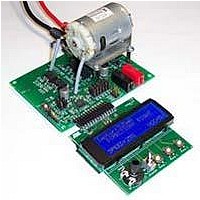
BOARD EVALUATION FOR ATA6823
Manufacturer
Atmel
Type
PWM Controllersr
Specifications of ATA6823-DK
Main Purpose
Power Management, Motor Control
Embedded
No
Utilized Ic / Part
ATA6823
Primary Attributes
Brush DC Motors, 8 ~ 18V, LIN Interface, Watchdog, 5V Regulator
Secondary Attributes
Cross Conduction, Under/Over Voltage, Short Circuit, & Temperature Protection
Input Voltage
8 V to 18 V
Product
Power Management Modules
Lead Free Status / RoHS Status
Contains lead / RoHS non-compliant
For Use With/related Products
ATA6823


6. Operating Range
The operating conditions define the limits for functional operation and parametric characteristics of the device. Functionality outside these
limits is not implied unless otherwise stated explicitly.
7. Noise and Surge Immunity, ESD and Latch-up
16
Parameters
Operating supply voltage
Operating supply voltage
Operating supply voltage
Operating supply voltage
Operating supply voltage
Operating supply voltage
Normal functionality
Normal functionality, overtemperature warning
Drivers for H1, H2, L1, L2, and LIN are switched
OFF, VCC regulator is OFF
Note:
Parameters
Conducted interferences
Conducted disturbances
ESD according to IBEE LIN EMC
- Pins LIN, PBAT, VBAT
- Pin EN2 (33k serial resistor)
ESD HBM with 1.5k /100pF
ESD HBM with 1.5k /100pF
Pins EN2, LIN, PBAT, VBAT against GND
ESD CDM (field induced method)
Note:
1. Full functionality
2. H-bridge drivers are switched off (undervoltage detection)
3. H-bridge drivers are switched off, 5V/3.3V regulator with reduced parameters, RESET works correctly
4. H-bridge drivers are switched off, 5V regulator not working, RESET not correct
5. H-bridge drivers are switched off
6. Full LIN functionality in conformance with LIN specification 2.1
1. Test pulse 5: V
Atmel ATA6823
(1)
(2)
(3)
(4)
(5)
(6)
bat max
Static latch-up tested according to AEC-Q100-004 and JESD78.
In test, the voltage at the pins VBAT, LIN, CP, VBATSW, Hx, and Sx must not exceed 45V
when not able to drive the specified current.
• 3 to 6 samples, 0 failures
• Electrical post stress testing at room temperature
= 40V
Standard and Test Conditions
ISO 7637-1
CISP25
Test specification 1.0 following IEC 61000-4-2
ESD- STM5.1-2001
JESD22-A114E 2007
CEI/IEC 60749-26: 2006
AEC-Q100-002-Ref_D
ESD- STM5.1-2001
JESD22-A114E 2007
CEI/IEC 60749-26: 2006
AEC-Q100-002-Ref_D
ESD STM5.3.1 - 1999
Symbol
V
V
V
V
V
V
VBAT1
VBAT2
VBAT3
VBAT4
VBAT5
VBAT6
T
T
T
j
j
j
> V
V
Min.
–40
150
165
THUV
6
3
0
7
THOV
V
V
±6kV
±5kV
±4kV
±8kV
±1kV
Max.
+150
165
180
< 6
< 3
THOV
THUV
40
18
Level 4
Level 5
Value
4856K–AUTO–01/11
(1)
Unit
°C
°C
°C
V
V
V
V
V
V
Related parts for ATA6823-DK
Image
Part Number
Description
Manufacturer
Datasheet
Request
R

Part Number:
Description:
IC H-BRIDGE MOTOR DRIVER 32-QFN
Manufacturer:
Atmel
Datasheet:

Part Number:
Description:
Motor / Motion / Ignition Controllers & Drivers Gate Driver IC
Manufacturer:
Atmel
Datasheet:

Part Number:
Description:
H-bridge Motor Driver
Manufacturer:
ATMEL Corporation
Datasheet:

Part Number:
Description:
DEV KIT FOR AVR/AVR32
Manufacturer:
Atmel
Datasheet:
Part Number:
Description:
INTERVAL AND WIPE/WASH WIPER CONTROL IC WITH DELAY
Manufacturer:
ATMEL Corporation
Datasheet:
Part Number:
Description:
Low-Voltage Voice-Switched IC for Hands-Free Operation
Manufacturer:
ATMEL Corporation
Datasheet:
Part Number:
Description:
MONOLITHIC INTEGRATED FEATUREPHONE CIRCUIT
Manufacturer:
ATMEL Corporation
Datasheet:
Part Number:
Description:
AM-FM Receiver IC U4255BM-M
Manufacturer:
ATMEL Corporation
Datasheet:
Part Number:
Description:
Monolithic Integrated Feature Phone Circuit
Manufacturer:
ATMEL Corporation
Datasheet:
Part Number:
Description:
Multistandard Video-IF and Quasi Parallel Sound Processing
Manufacturer:
ATMEL Corporation
Datasheet:
Part Number:
Description:
High-performance EE PLD
Manufacturer:
ATMEL Corporation
Datasheet:
Part Number:
Description:
8-bit Flash Microcontroller
Manufacturer:
ATMEL Corporation
Datasheet: