ATA6823-DK Atmel, ATA6823-DK Datasheet - Page 5
ATA6823-DK
Manufacturer Part Number
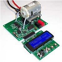
ATA6823-DK
Description
BOARD EVALUATION FOR ATA6823
Manufacturer
Atmel
Type
PWM Controllersr
Specifications of ATA6823-DK
Main Purpose
Power Management, Motor Control
Embedded
No
Utilized Ic / Part
ATA6823
Primary Attributes
Brush DC Motors, 8 ~ 18V, LIN Interface, Watchdog, 5V Regulator
Secondary Attributes
Cross Conduction, Under/Over Voltage, Short Circuit, & Temperature Protection
Input Voltage
8 V to 18 V
Product
Power Management Modules
Lead Free Status / RoHS Status
Contains lead / RoHS non-compliant
For Use With/related Products
ATA6823


3. Functional Description
3.1
3.1.1
3.1.2
3.1.3
4856K–AUTO–01/11
Power Supply Unit with Supervisor Functions
Power Supply
Voltage Supervisor
Temperature Supervisor
The IC is supplied by a reverse-protected battery voltage. To prevent it from destruction,
proper external protection circuitry has to be added. It is recommended to use at least a
capacitor combination of storage and HF caps behind the reverse protection circuitry and
closed to the VBAT pin of the IC (see
A fully-internal low-power and low-drop regulator, stabilized by an external blocking capacitor
provides the necessary low-voltage supply needed for the wake-up process. The low-power
band gap reference is trimmed and is used for the bigger VCC regulator, too. All internal
blocks are supplied by the internal regulator.
Note:
Nothing inside the IC except the logic interface to the microcontroller is supplied by the
5V/3.3V VCC regulator.
A power-good comparator checks the output voltage of the V
chip in reset as long as the voltage is too low.
There is a high-voltage switch which brings out the battery voltage to the pin VBATSW for
measurement purposes. This switch is switched ON for VCC = HIGH and stays ON in case of
a watchdog reset going to sleep mode, VBATSW turns OFF. The signal can be used to switch
on external voltage regulators, etc.
This block is intended to protect the IC and the external power MOS transistors against over-
voltage on battery level and to manage undervoltage on it.
Function: in case of both overvoltage alarm (V
external NMOS motor bridge transistors will be switched off. The failure state will be flagged
via DG2. No other actions will be carried out. The voltage supervision block is connected to
VBAT and filtered by a first-order low pass with a corner frequency of typical 15kHz.
There is a temperature sensor integrated on-chip to prevent the IC from overheating due to a
failure in the external circuitry and to protect the external NMOSFET transistors.
In case of detected overtemperature (150°C), the diagnostic pin DG3 will be switched to “H” to
signalize this event to the microcontroller. It should undertake actions to reduce the power dis-
sipation in the IC. In case of detected overtemperature (165°C), the V
drivers including the LIN transceiver will be switched OFF immediately and /RESET will go
LOW.
Both temperature thresholds are correlated. The absolute tolerance is ±10°C and there is a
built-in hysteresis of about 10°C to avoid fast oscillations. After cooling down below the 155°C
threshold; the IC will go into Active mode.
The LIN interface has a separate thermal shutdown with disabled the low-side driver at typi-
cally 165°C.
The internal supply voltage V
INT
must not be used for any other supply purpose!
Figure 1-1 on page
THOV
) and of undervoltage alarm (V
2).
INT
regulator and keeps the whole
Atmel ATA6823
CC
regulator and all
THUV
) the
5
Related parts for ATA6823-DK
Image
Part Number
Description
Manufacturer
Datasheet
Request
R

Part Number:
Description:
IC H-BRIDGE MOTOR DRIVER 32-QFN
Manufacturer:
Atmel
Datasheet:

Part Number:
Description:
Motor / Motion / Ignition Controllers & Drivers Gate Driver IC
Manufacturer:
Atmel
Datasheet:

Part Number:
Description:
H-bridge Motor Driver
Manufacturer:
ATMEL Corporation
Datasheet:

Part Number:
Description:
DEV KIT FOR AVR/AVR32
Manufacturer:
Atmel
Datasheet:
Part Number:
Description:
INTERVAL AND WIPE/WASH WIPER CONTROL IC WITH DELAY
Manufacturer:
ATMEL Corporation
Datasheet:
Part Number:
Description:
Low-Voltage Voice-Switched IC for Hands-Free Operation
Manufacturer:
ATMEL Corporation
Datasheet:
Part Number:
Description:
MONOLITHIC INTEGRATED FEATUREPHONE CIRCUIT
Manufacturer:
ATMEL Corporation
Datasheet:
Part Number:
Description:
AM-FM Receiver IC U4255BM-M
Manufacturer:
ATMEL Corporation
Datasheet:
Part Number:
Description:
Monolithic Integrated Feature Phone Circuit
Manufacturer:
ATMEL Corporation
Datasheet:
Part Number:
Description:
Multistandard Video-IF and Quasi Parallel Sound Processing
Manufacturer:
ATMEL Corporation
Datasheet:
Part Number:
Description:
High-performance EE PLD
Manufacturer:
ATMEL Corporation
Datasheet:
Part Number:
Description:
8-bit Flash Microcontroller
Manufacturer:
ATMEL Corporation
Datasheet: