ATA6823-DK Atmel, ATA6823-DK Datasheet - Page 12
ATA6823-DK
Manufacturer Part Number
ATA6823-DK
Description
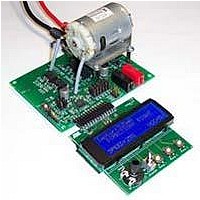
BOARD EVALUATION FOR ATA6823
Manufacturer
Atmel
Type
PWM Controllersr
Specifications of ATA6823-DK
Main Purpose
Power Management, Motor Control
Embedded
No
Utilized Ic / Part
ATA6823
Primary Attributes
Brush DC Motors, 8 ~ 18V, LIN Interface, Watchdog, 5V Regulator
Secondary Attributes
Cross Conduction, Under/Over Voltage, Short Circuit, & Temperature Protection
Input Voltage
8 V to 18 V
Product
Power Management Modules
Lead Free Status / RoHS Status
Contains lead / RoHS non-compliant
For Use With/related Products
ATA6823


3.8
3.9
3.10
3.11
12
Charge Pump
Thermal Shutdown
H-bridge Driver
VG Regulator
Atmel ATA6823
Table 3-2.
In order to be able to distinguish between a wake-up from LIN or from EN2, the source of
wake-up is flagged in DG1 until the first valid trigger (LIN = 0, EN2 = 1).
The VG regulator is used to generate the gate voltage for the low-side driver. Its output voltage
will be used as one input for the charge pump, which generates the gate voltage for the
high-side driver. The purpose of the regulator is to limit the gate voltage for the external power
MOS transistors to 12V. It needs a ceramic capacitor of 470nF for stability. The output voltage
is reduced if the supply voltage at VBAT falls below 12V.
The integrated charge pump is needed to supply the gates of the external power MOS transis-
tors. It needs a shuffle capacitor of 220nF and a reservoir capacitor of 470nF. Without load,
the output voltage on the reservoir capacitor is V
with a dedicated internal oscillator of 100KHz. The charge pump is designed to reach a good
EMC level.
There is a thermal shutdown block implemented. With rising junction temperature, a first warn-
ing level will be reached at 150°C. At this point the IC stays fully functional and a warning will
be sent to the microcontroller. At junction temperature 165°C the VCC regulator will be
switched off and a reset occurs.
The IC includes two push-pull drivers for control of two external power NMOS used as
high-side drivers and two push-pull drivers for control of two external power NMOS used as
low-side drivers. The drivers are able to be used with standard and logic-level power NMOS.
The drivers for the high-side control use the charge pump voltage to supply the gates with a
voltage of VG above the battery voltage level. The low-side drivers are supplied by VG
directly. It is possible to control the external load (motor) in the forward and reverse direction
(see
100% is possible in both directions.
Note:
CPOK
0
X
X
X
X
Table 3-1 on page
OT1: Overtemperature warning
OV: Overvoltage of VBAT
UV: Undervoltage of VBAT
SC: Short circuit
CPOK: Charge pump OK
X represents: don't care – no effect)
OT1
X
X
X
X
1
Device Status
Status of the Diagnostic Outputs
OV
X
X
X
X
1
11). The duty cycle of the PMW controls the speed. A duty cycle of
UV
X
X
X
X
1
SC
X
X
X
X
1
DG1
–
–
–
–
1
Diagnostic Outputs
DG2
VBAT
1
–
1
1
–
plus VG. The charge pump is clocked
DG3
–
1
–
–
–
Overtemperature warning
Charge pump failure
Undervoltage
Overvoltage
Short circuit
Comments
4856K–AUTO–01/11
Related parts for ATA6823-DK
Image
Part Number
Description
Manufacturer
Datasheet
Request
R

Part Number:
Description:
IC H-BRIDGE MOTOR DRIVER 32-QFN
Manufacturer:
Atmel
Datasheet:

Part Number:
Description:
Motor / Motion / Ignition Controllers & Drivers Gate Driver IC
Manufacturer:
Atmel
Datasheet:

Part Number:
Description:
H-bridge Motor Driver
Manufacturer:
ATMEL Corporation
Datasheet:

Part Number:
Description:
DEV KIT FOR AVR/AVR32
Manufacturer:
Atmel
Datasheet:
Part Number:
Description:
INTERVAL AND WIPE/WASH WIPER CONTROL IC WITH DELAY
Manufacturer:
ATMEL Corporation
Datasheet:
Part Number:
Description:
Low-Voltage Voice-Switched IC for Hands-Free Operation
Manufacturer:
ATMEL Corporation
Datasheet:
Part Number:
Description:
MONOLITHIC INTEGRATED FEATUREPHONE CIRCUIT
Manufacturer:
ATMEL Corporation
Datasheet:
Part Number:
Description:
AM-FM Receiver IC U4255BM-M
Manufacturer:
ATMEL Corporation
Datasheet:
Part Number:
Description:
Monolithic Integrated Feature Phone Circuit
Manufacturer:
ATMEL Corporation
Datasheet:
Part Number:
Description:
Multistandard Video-IF and Quasi Parallel Sound Processing
Manufacturer:
ATMEL Corporation
Datasheet:
Part Number:
Description:
High-performance EE PLD
Manufacturer:
ATMEL Corporation
Datasheet:
Part Number:
Description:
8-bit Flash Microcontroller
Manufacturer:
ATMEL Corporation
Datasheet: