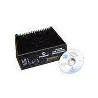
DM300022 Microchip Technology, DM300022 Datasheet - Page 21

DM300022
Manufacturer Part Number
DM300022
Description
MODULE PWR DSPICDEM MC1L LV 3PHS
Manufacturer
Microchip Technology
Specifications of DM300022
Main Purpose
Power Management, Motor Control
Embedded
Yes, MCU, 16-Bit
Utilized Ic / Part
dsPIC33FJxxxMC
Primary Attributes
3-Phase Low Voltage Power Module
Secondary Attributes
Motion Sensor Inputs: Hall Sensors or Optical Encoder
Silicon Manufacturer
Microchip
Silicon Core Number
DsPICDEM MC1L
Kit Application Type
Power Management - Motor Control
Application Sub Type
3 Phase Motor
Silicon Family Name
Piccolo
Rohs Compliant
Yes
Lead Free Status / RoHS Status
Lead free / RoHS Compliant
© 2003 Microchip Technology Inc.
1.4.2
The inverter is capable of providing the full rated output of 15A (RMS) within the entire
operating range (voltage, temperature and at up to 20 kHz modulation frequency) of
the system. This includes being continuously stalled at such an electrical angle that
one of the motor phases is at the peak of the rated output (21A) at just less than 100%
duty cycle. This is a condition that causes high thermal loading because one of the
inverter switches has the peak worst case conduction and switching loss continuously.
Note that as far as the power devices are concerned, operation at output frequencies
of less than approximately 10 Hz are equivalent to stall as far as peak device
temperature is concerned because of low thermal capacitance.
In a practical application, this condition of low output frequency/stall and high duty
cycle is unlikely to happen. With a motor correctly matched to the DC bus voltage, the
switch duty cycle at stall will be approximately 50% thus significantly reducing the
conduction loss in a particular switch. The complementary diode of the inverter phase
will also conduct for approximately 50% thus spreading the conduction loss between
two different power device packages. This in turn leads to a substantial reduction in
device temperature.
As the maximum output current is fixed, the maximum possible output power is
linearly related to the DC input voltage.
1.4.3
The continuous rated input current is limited to 15A RMS by the allowable tempera-
ture rise of the tracking on the PCB. Short term (10s duration with a low duty cycle)
overloads to 20A RMS are permitted. The overload is limited by the reverse voltage
protection MOSFET dissipation and the PCB tracking.
1.4.4
The brake chopper switch and diode are capable of providing the full rated output of
20A (peak) within the entire operating range (voltage, temperature and at up to 16 kHz
modulation frequency) of the system provided the load is predominantly resistive. If
the brake chopper is being used to control a load that is predominantly inductive, the
rated output must be reduced to 10A (peak) in order to protect the diode from thermal
overload. This is because the current may be continuous with an inductive load, which
will significantly increase the proportion of the current that flows through the diode.
The user should note that the over current trip levels are set above the peak of the
rated output. This is to prevent nuisance trips. The user should avoid operating the
system beyond the peak outputs of 20A (resistive load) or 10A (inductive load)
continuously. Operation of the system just beneath the over-current trip of 24.5A may
affect long term reliability of the brake chopper switch and diode and should be
avoided. The value of the brake chopper resistor should be chosen to ensure no more
than 20A can flow, even at the peak DC bus voltage.
Inverter Output Current Limits
DC Input Current Limits
Brake Chopper Output Current Limits
Set Up and Operation
DS70097A-page 15


