DM300022 Microchip Technology, DM300022 Datasheet - Page 22
DM300022
Manufacturer Part Number
DM300022
Description
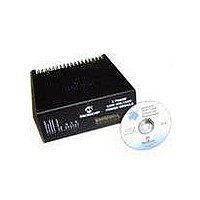
MODULE PWR DSPICDEM MC1L LV 3PHS
Manufacturer
Microchip Technology
Specifications of DM300022
Main Purpose
Power Management, Motor Control
Embedded
Yes, MCU, 16-Bit
Utilized Ic / Part
dsPIC33FJxxxMC
Primary Attributes
3-Phase Low Voltage Power Module
Secondary Attributes
Motion Sensor Inputs: Hall Sensors or Optical Encoder
Silicon Manufacturer
Microchip
Silicon Core Number
DsPICDEM MC1L
Kit Application Type
Power Management - Motor Control
Application Sub Type
3 Phase Motor
Silicon Family Name
Piccolo
Rohs Compliant
Yes
Lead Free Status / RoHS Status
Lead free / RoHS Compliant


dsPICDEM™ MC1L 3-Phase Low Voltage Power Module
1.5
DS70097A-page 16
DETAILED DESCRIPTION OF OPERATION
1.5.1
The input stage of the board consists of the following components:
• F1 – 1.25" x 0.25" 125 VDC 15A High Rupture Current Fuse - Note: only replace
• C9, C10 – Film capacitors to aid in the suppression of supply borne transients and
• V1 – A metal oxide varistor located across the incoming supply lines to suppress
1.5.2
1.5.2.1
As is normal for a low voltage system, soft-start protection is not provided within the
unit. The NTC (NTC1) on the PCB is replaced by a wire link. When using a
current-limiting DC power supply, this will cause no problem as the inrush of current
on application of DC power, due to the DC bus capacitors, will be controlled. If using a
substantial battery supply, the user may need to provide some form of soft-start to
prevent the fuse blowing on power-up. If fitting a device to NTC1 on the PCB, the user
should carefully monitor the temperature of the PCB around it.
1.5.2.2
In order to protect the unit from accidental reversal of the input voltage, a circuit has
been included which blocks the reverse voltage. Although a series diode could have
been used, this would have incurred a very significant amount of loss during normal
running. The circuit used is described below:
• Q9 – A 75V 13 mΩ (cold) MOSFET of the same type used for the inverter. During
• D32, R6 and R58 – The gate drive components for Q9. During normal operation,
1.5.3
1.5.3.1
The 3-phase inverter has three identical circuits, shown as R (RED), Y (YELLOW) and
B (BLUE). These are often referred to as inverter "legs". They invert the DC bus to a
variable AC output waveform by appropriate modulation of the switches. When a star
or delta connected three-phase motor is used, the electrical symmetry can be
exploited to provide bi-directional current and voltage with just three such legs. In this
way, both motoring and generating/braking operation can be used in either direction of
rotation, commonly called "4 Quadrant" control.
with part of the same rating.
to also provide a low impedance return path for any currents that flows from the
power device tabs to the heat-sink and enclosure due to capacitive coupling.
high energy transients.
normal operation (correct polarity of input voltage), the MOSFET is turned on with
current flowing from source to drain. The voltage drop will be due to the resistance
of the MOSFET, rather than that of a diode. When reverse polarity is applied, Q9
is turned off and blocks the reverse voltage.
Q9 is turned on via R6 with D32 limiting the gate source voltage to 15V. On
application of reverse voltage, Q9 turns off with R59 being a gate source
pull-down.
Input Stage (Appendix A Sheet 1)
Input Power Stage (Appendix A Sheet 1)
SOFT-START PROTECTION
REVERSE VOLTAGE PROTECTION
Phase Inverter (Appendix A Sheet 2)
INTRODUCTION
© 2003 Microchip Technology Inc.
Related parts for DM300022
Image
Part Number
Description
Manufacturer
Datasheet
Request
R

Part Number:
Description:
Manufacturer:
Microchip Technology Inc.
Datasheet:
Part Number:
Description:
Manufacturer:
Microchip Technology Inc.
Datasheet:
Part Number:
Description:
Manufacturer:
Microchip Technology Inc.
Datasheet:
Part Number:
Description:
Manufacturer:
Microchip Technology Inc.
Datasheet:
Part Number:
Description:
Manufacturer:
Microchip Technology Inc.
Datasheet:
Part Number:
Description:
Manufacturer:
Microchip Technology Inc.
Datasheet:
Part Number:
Description:
Manufacturer:
Microchip Technology Inc.
Datasheet:
Part Number:
Description:
Manufacturer:
Microchip Technology Inc.
Datasheet: