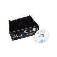
DM300022 Microchip Technology, DM300022 Datasheet - Page 33

DM300022
Manufacturer Part Number
DM300022
Description
MODULE PWR DSPICDEM MC1L LV 3PHS
Manufacturer
Microchip Technology
Specifications of DM300022
Main Purpose
Power Management, Motor Control
Embedded
Yes, MCU, 16-Bit
Utilized Ic / Part
dsPIC33FJxxxMC
Primary Attributes
3-Phase Low Voltage Power Module
Secondary Attributes
Motion Sensor Inputs: Hall Sensors or Optical Encoder
Silicon Manufacturer
Microchip
Silicon Core Number
DsPICDEM MC1L
Kit Application Type
Power Management - Motor Control
Application Sub Type
3 Phase Motor
Silicon Family Name
Piccolo
Rohs Compliant
Yes
Lead Free Status / RoHS Status
Lead free / RoHS Compliant
1.6
© 2003 Microchip Technology Inc.
MODIFYING THE BOARD
1.5.9.6
The signals from the three Hall effect current transducers are used to provide
protection against overload, wiring and earth (ground) faults. The two inverter output
Halls (U3 and U4) are checked for both positive and negative current. The DC input
Hall (U2) is only checked for positive current. The circuitry to implement the trip is
shown on Sheet 6 of Appendix A. Being similar to that described in Section
1.5.9.2 “Inverter Shunt Over-current”, it requires little further explanation. The one
difference is that the input signals to the comparator are divided down in order to stay
within the input voltage limitations of the comparators when running from +5V.
1.6.1
Certain modifications have been allowed for in the design of the system, as described
below. Clearly, any additional modifications that the user chooses to make can not be
guaranteed to be functional or safe. It is assumed that relevant qualified personnel
only will use the system.
1.6.2
Before removing the lid of the system, the following procedure should be rigidly
followed:
• Turn off all power to the system.
• Wait a minimum of 5 minutes so that the internal discharge circuit has reduced the
• Verify with a voltmeter that discharge has taken place by checking the potential
• The system is now safe to work on.
• Remove all cables from the system.
• Remove the screws fixing the lid to the chassis and heat sink on the top and
• Slide the lid forwards while holding the unit by the heat sink.
1.6.3
• Provision has been made to change the current feedback scaling of both the
• Follow the procedure given in Section 1.6.2 “Accessing The System” for
• Changing the inverter leg shunt sensing between unipolar and bipolar is
DC bus voltage to a safe level. The red LED bus voltage indicator visible through
the top ventilation holes should be out.
between the + and - DC terminals of the 7-pin output connector before
proceeding. The voltage should be less than 5V.
bottom.
isolated Hall transducers and the inverter leg and bus shunts. As the trip levels
are set at a fixed voltage, changing the feedback scaling also changes the trip
levels. Changing the scaling is accomplished in the following way:
accessing the unit.
accomplished with LK4. LK4 is located directly under the "Danger High Voltage"
label on the PCB. Table 1-6 shows the settings:
HALL OVER-CURRENT
Introduction
Accessing The System
Changing Current Feedback and Trip Scaling
Set Up and Operation
DS70097A-page 27


