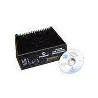
DM300022 Microchip Technology, DM300022 Datasheet - Page 23

DM300022
Manufacturer Part Number
DM300022
Description
MODULE PWR DSPICDEM MC1L LV 3PHS
Manufacturer
Microchip Technology
Specifications of DM300022
Main Purpose
Power Management, Motor Control
Embedded
Yes, MCU, 16-Bit
Utilized Ic / Part
dsPIC33FJxxxMC
Primary Attributes
3-Phase Low Voltage Power Module
Secondary Attributes
Motion Sensor Inputs: Hall Sensors or Optical Encoder
Silicon Manufacturer
Microchip
Silicon Core Number
DsPICDEM MC1L
Kit Application Type
Power Management - Motor Control
Application Sub Type
3 Phase Motor
Silicon Family Name
Piccolo
Rohs Compliant
Yes
Lead Free Status / RoHS Status
Lead free / RoHS Compliant
© 2003 Microchip Technology Inc.
There is no reason why the user can not use two of the legs in an "H-bridge"
configuration for control of DC motors or other single-phase applications requiring
bi-directional current and voltage. Even a single leg could be used with just the low
side switch controlled for a simple unidirectional current application (e.g., field control
of a separately excited DC motor).
The detailed description of one "leg" (RED phase) is given below. The other legs are
identical in function.
1.5.3.2
• Q3, Q4 – 75V N-Channel MOSFET transistors packaged in the industry standard
• The tracking between the devices and to the DC bus is designed to minimize the
• R4 – A 3W 5 mW shunt resistor through which the low side switch and diode
1.5.3.3
• U22 – An integrated high voltage IC (IR 2112) which provides gate control of a low
The function of groups of the discrete gate drive components is explained below:
• R51, D28, C14, C17 – These components form a floating power supply for the
TO220. As the tabs of the devices are not isolated, a thermally conductive
insulator is used. Note that the internal parasitic body diodes of the MOSFETs are
used as the inverter freewheeling diodes.
inductance that causes transient over/undershoots.
returns to the -DC bus. The shunt is used for FAULT protection and (optionally) for
an alternative feedback signal - see Section 1.2.7 “FAULT Protection” and
Section 1.5.6 “Shunt Feedback (Appendix A Sheet 3)”.
side and a high side power transistor. As the source of the high side device (Q3)
can be at any potential between -DC and +DC, and even beyond transiently,
internal circuitry must provide for the necessary level shifting to ensure correct
operation. The IR2112 does this without providing isolation. The 2112 also
monitors the low and high side power supplies and shuts down if an under voltage
is detected. The under-voltage lockout is automatically reset by a rising edge of a
firing command once a valid voltage is present. See www.irf.com for a full data
sheet.
high side gate driving stage of U22. Whenever the low side MOSFET (Q4) or it's
anti-parallel diode is conducting, a charging path for C14 and C17 is formed. This
is because the 15V supply is referenced to the -DC bus and D28 conducts. When
the high side switch is on, and the low side switch is therefore off, D28 blocks
reverse current flow that would result from the bus voltage present on the inverter
output. This kind of floating supply is usually referred to as a "bootstrap". This
circuit is commonly used because it is both efficient and economical. It is
assumed that any bootstrap initial priming or any necessary refresh is carried out
in software by the dsPIC device. This is discussed in Section 1.2.5 “Modulating
The Power Devices”.
POWER DEVICES
GATE DRIVE
Set Up and Operation
DS70097A-page 17


