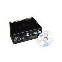
DM300022 Microchip Technology, DM300022 Datasheet - Page 35

DM300022
Manufacturer Part Number
DM300022
Description
MODULE PWR DSPICDEM MC1L LV 3PHS
Manufacturer
Microchip Technology
Specifications of DM300022
Main Purpose
Power Management, Motor Control
Embedded
Yes, MCU, 16-Bit
Utilized Ic / Part
dsPIC33FJxxxMC
Primary Attributes
3-Phase Low Voltage Power Module
Secondary Attributes
Motion Sensor Inputs: Hall Sensors or Optical Encoder
Silicon Manufacturer
Microchip
Silicon Core Number
DsPICDEM MC1L
Kit Application Type
Power Management - Motor Control
Application Sub Type
3 Phase Motor
Silicon Family Name
Piccolo
Rohs Compliant
Yes
Lead Free Status / RoHS Status
Lead free / RoHS Compliant
© 2003 Microchip Technology Inc.
TABLE 1-9:
Once the modification is complete, install the lid ensuring all the screws are replaced.
1.6.3.1
The voltage feedback scaling is configured for the maximum range of input voltages. If
the user requires full ADC resolution at lower voltages, then this can easily be
accomplished by changing the high voltage resistors mounted on the top of the PCB.
• Follow the procedure given in Section 1.6.2 “Accessing The System” for
• To change DC bus voltage scaling, modify R10, R13, R14. Note, if using the back
• To change phase voltage scaling modify R16 - R20.
• In all cases, it is suggested that the changes are made from the top of the board.
• Once the modification is complete, install the lid ensuring all the screws are
1.6.3.2
The type of braking resistor installed on the heat sink allows a maximum continuous
dissipation of 50W, but can tolerate many times this power level for short periods. The
value installed as standard only allows a maximum dissipation of 45W owing to its
high resistance. If the user wishes to change the resistor to a lower value or remove
the resistor completely as they are using an external resistor, then they should follow
the procedure given below.
• Follow the procedure given in Section 1.6.2 “Accessing The System” for
• De-solder or cut the wires to J7 and J8. This can be done from the top of the PCB.
• Undo the screws attaching the resistor to the heat sink and remove the resistor
• If not fitting a new resistor proceed to the last step.
• Make up a wiring assembly for the new resistor with similar lead lengths and the
• Apply a thin, even coating of thermally conductive heat sink compound (e.g.,
accessing the unit.
EMF crossing detection circuitry (see Section 1.5.7.3 “Inverter Output Voltage
Feedback and Sensorless Detection”), the user should also change the phase
voltage feedback resistors to ensure consistent scaling.
If new component legs are inserted, these should be cropped to ensure that the
maximum length of lead protruding below the PCB is 4 mm.
replaced.
accessing the unit.
and its wiring.
terminals protected with heat shrink sleeving. Ensure the wire has sufficient
current and voltage rating.
Dow-Corning 340) to the back of the resistor.
Note: Important: For the system, as delivered, the highest current range (LK3,
Scaling (A / V)
Trip Level (A)
CHANGING VOLTAGE FEEDBACK AND TRIP SCALING
MODIFYING OR REMOVING THE INTERNAL BRAKING RESISTOR
LK13 and LK16) should not be used. This is because of thermal limitations
of the power devices. If the user requires less current, then using the lowest
current range (LK1) will give improved current feedback range and
resolution.
HALL EFFECT CURRENT TRANSDUCER SCALING SELECTION
LK1/LK15/LK18
Closed
±14.8
8
LK2/LK14/LK17
Set Up and Operation
Closed
±22.2
12
LK3/LK13/LK16
DS70097A-page 29
Closed
±44.4
24


