DM300022 Microchip Technology, DM300022 Datasheet - Page 36
DM300022
Manufacturer Part Number
DM300022
Description
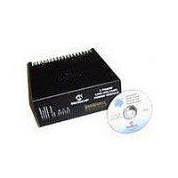
MODULE PWR DSPICDEM MC1L LV 3PHS
Manufacturer
Microchip Technology
Specifications of DM300022
Main Purpose
Power Management, Motor Control
Embedded
Yes, MCU, 16-Bit
Utilized Ic / Part
dsPIC33FJxxxMC
Primary Attributes
3-Phase Low Voltage Power Module
Secondary Attributes
Motion Sensor Inputs: Hall Sensors or Optical Encoder
Silicon Manufacturer
Microchip
Silicon Core Number
DsPICDEM MC1L
Kit Application Type
Power Management - Motor Control
Application Sub Type
3 Phase Motor
Silicon Family Name
Piccolo
Rohs Compliant
Yes
Lead Free Status / RoHS Status
Lead free / RoHS Compliant


dsPICDEM™ MC1L 3-Phase Low Voltage Power Module
DS70097A-page 30
• Fit the resistor to the heat sink and solder the wires into J7 and J8. Ensure the
• Once the modification is complete, install the lid ensuring all the screws are
Note that if the user fits a lower value of internal resistor to allow higher transient
dissipation, then the user's software must ensure adequate thermal protection for the
resistor. Failure to do so can cause the resistor to rupture. Consult the manufacturers
data sheet carefully.
1.6.3.3
The reverse voltage protection MOSFET dissipates an appreciable amount of power.
If the user is satisfied that this is not required, they can easily remove it by using the
following procedure. Alternatively, the user can use the auxiliary DC input on the 7-pin
output connector but this also bypasses the DC input current transducer and its
associated trip protection.
• Follow the procedure given in Section 1.6.2 “Accessing The System” for
• To remove the reverse voltage protection MOSFET Q9, undo the clip mounting
• Once the modification is complete, install the lid ensuring all the screws are
1.6.3.4
All the non-isolated feedback signals are brought to a series of links that run along the
edge of the isolation barrier. In order to access these signals, the user should rigidly
carry out the procedure given below. Failure to do so could represent a safety hazard
to the user.
• Follow the procedure given in Section 1.6.2 “Accessing The System” for
• Disconnect the input wiring from the DC supply outlet.
• Ensure that the earth (ground) continuity is maintained to the unit.
• In order to make the links for the non-isolated signals, it is recommended that two
• Note that all signals to and from the system are now referenced to the -DC bus
• Once the modification is complete, install the lid ensuring all the screws are
leads are cropped so that the maximum length of lead protruding below the PCB
is 4 mm.
replaced.
accessing the unit.
the device and de-solder it from the top of the PCB. Solder a wire link between
pads 2 and 3 of a suitable rating having cropped the leads, ensuring that the
maximum length of lead protruding below the PCB is 4 mm.
replaced.
accessing the unit.
0.3" pitch, 14-pin DIL resistor packages are used. These should be of the
"straight-through" type with 7 independent resistors. The suggested value is
330Ω, as this will provide some ESD protection without too high a source
impedance being introduced. Note that LK28 has no circuit connections and is
provided to allow the second DIL resistor package to be installed. If the user
decides to fit links or individual resistors, these should be installed so that not
more than 4 mm of lead protrudes beneath the PCB.
that is at earth (ground) potential. The Digital 0V of the control card is permanently
connected to the enclosure chassis and is therefore also referenced to ground.
replaced.
BYPASSING THE REVERSE VOLTAGE PROTECTION
ACCESSING THE ADDITIONAL (NON-ISOLATED) FEEDBACK SIGNALS
© 2003 Microchip Technology Inc.
Related parts for DM300022
Image
Part Number
Description
Manufacturer
Datasheet
Request
R

Part Number:
Description:
Manufacturer:
Microchip Technology Inc.
Datasheet:
Part Number:
Description:
Manufacturer:
Microchip Technology Inc.
Datasheet:
Part Number:
Description:
Manufacturer:
Microchip Technology Inc.
Datasheet:
Part Number:
Description:
Manufacturer:
Microchip Technology Inc.
Datasheet:
Part Number:
Description:
Manufacturer:
Microchip Technology Inc.
Datasheet:
Part Number:
Description:
Manufacturer:
Microchip Technology Inc.
Datasheet:
Part Number:
Description:
Manufacturer:
Microchip Technology Inc.
Datasheet:
Part Number:
Description:
Manufacturer:
Microchip Technology Inc.
Datasheet: