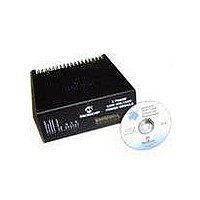
DM300022 Microchip Technology, DM300022 Datasheet - Page 24

DM300022
Manufacturer Part Number
DM300022
Description
MODULE PWR DSPICDEM MC1L LV 3PHS
Manufacturer
Microchip Technology
Specifications of DM300022
Main Purpose
Power Management, Motor Control
Embedded
Yes, MCU, 16-Bit
Utilized Ic / Part
dsPIC33FJxxxMC
Primary Attributes
3-Phase Low Voltage Power Module
Secondary Attributes
Motion Sensor Inputs: Hall Sensors or Optical Encoder
Silicon Manufacturer
Microchip
Silicon Core Number
DsPICDEM MC1L
Kit Application Type
Power Management - Motor Control
Application Sub Type
3 Phase Motor
Silicon Family Name
Piccolo
Rohs Compliant
Yes
Lead Free Status / RoHS Status
Lead free / RoHS Compliant
dsPICDEM™ MC1L 3-Phase Low Voltage Power Module
DS70097A-page 18
FIGURE 1-5:
• R33, D21, R39 and R38 – These components aid in the correct control of the gate
• D31 – This is a high voltage clamping diode located directly adjacent to the IC. It
• R27 and R26 – These resistors form a passive Gate Source pull-down to ensure
1.5.4
Clearly, if the motor is used as a brake or generator, any average power that flows
back from the inverter must have somewhere to go. As most DC supplies, with the
exception of batteries, will not sink current, a circuit for dissipating excess returned
power is provided. The most common form of brake chopper has been implemented
and is described below:
• Q10 – A 75V N-Channel MOSFET transistor of the same type as used for the
• D3 – A 8A 200V diode required to freewheel the current around the resistor due to
• R9 – A 3W 5 mW shunt resistor through which the low side switch and diode
• U23 – Microchip TC1412N gate drive IC. This contains a low resistance comple-
of the high side power device. The same circuit is repeated for the low side switch
using R54, D27, R57 and R58. Generally speaking, the larger value of gate
resistance used, the slower the device switches. Slower switching reduces
over/undershoots and consequently EMI, but increases switching loss and hence
device junction temperature. Turning the device on uses R39 and R38. Turning
the device off uses D21+R33 in parallel with R39 and R38. In this way, different
turn on and turn off resistance can be used to optimize switching performance.
is necessary to ensure correct operation of the IC during extreme transients that
can occur during a FAULT. In combination with R38 and R53, it ensures Pin 6 of
U22 never goes more than 5V negative with respect to Pin 2.
the MOSFETs stay off if the low voltage power supplies are not present.
inverter. Apart from acoustic noise reasons, there is no reason to modulate the
device at high frequency. As the tab of the device is not isolated, a thermally
conductive insulator is used.
it's inductance. As the tab of the device is not isolated, a thermally conductive
insulator is used.
returns to the -DC bus. The shunt is used for FAULT protection and (optionally) for
an alternative feedback signal - see Section 1.2.7 “FAULT Protection” and
Section 1.5.6 “Shunt Feedback (Appendix A Sheet 3)”.
mentary push-pull MOSFET pair and input circuitry suitable for interfacing to a
wide range of input voltages. It has a small footprint allowing it to be located
physically close to the transistor, allowing a low inductance gate circuit layout.
Note that the full current drive capability of the TC1412N is not necessarily
required, as high frequency modulation is not essential for a brake chopper. A less
expensive TC1410N or TC1411N could be used.
Brake Chopper (Appendix A Sheet 1)
BOOTSTRAP SUPPLY
15V
R51
C17
R4
D28
Q4
R38
Bootstrap
Supply
© 2003 Microchip Technology Inc.


