EVAL6569 STMicroelectronics, EVAL6569 Datasheet
EVAL6569
Specifications of EVAL6569


Related parts for EVAL6569


EVAL6569 Summary of contents
Page 1
THE L6569: A NEW HIGH VOLTAGE IC DRIVER FOR INTRODUCTION Electronic lamp ballasts are now popular in both consumer and industrial lighting. They offer power saving, flicker free operation and reduced sizes. Improvements to the light control and cost ...
Page 2
AN880 APPLICATION NOTE THE L6569 AND ITS APPLICATIONS The L6569 The L6569 is able to directly control a symmetric half bridge inverter of a fluorescent lamp ballast low voltage halogen lamp transformer.Two 270mA buffers drive the inverter MOSFETs ...
Page 3
Figure 5: Bootstrap capacitor charge. 15.6 V L6569 Figure 6: Basic diagram for 2x10⁵ W lamp ballast in full bridge configuration L6569 CF EXTERNAL OSCILLATOR GND D02IN1386 Typical industrial TL ballasts requires complex control with ...
Page 4
AN880 APPLICATION NOTE The L6569A holds both MOSFETs OFF until the Under Voltage Lock Out is reached. This is in- tended for inverters using 2 decoupling capacitors in half bridge as shown on figure 12. The inverter is totally off, ...
Page 5
Figure 9. L6569 driver protection against voltage spikes. BV L6569 The auxiliary supply of the converter The circuit consumption is defined by the MOS- FETs gate charge, the I.C. consumption, the os- cillator, and the shunt regulator. Several circuits are ...
Page 6
AN880 APPLICATION NOTE charged and the circuit can restart immediately. This method is suitable when the inverter uses only one DC blocking capacitor connected to the power ground, as used on figure 11 for Compact Fluorescent Lamp. Pulling the V ...
Page 7
THE LAMP SEEN BY THE ELECTRONIC DE- SIGNER The lamp equivalent impedance The compact fluorescent lamps are specified at 25 kHz (IEC 929). The MOSFETs and the L6569 allow to increase the switching frequency, but the sensitivity of the lamp ...
Page 8
AN880 APPLICATION NOTE as a transformer supplying the voltage to the fila- ments. Only few components are added around the L6569 (see figure 18), and the control of the preheat energy is less sensitive to the preheat du- ration and ...
Page 9
V is applied when the oscillator DC starts. The ballast has to start directly with its nominal conditions to remove any transient oscil- lation. Hence the operation runs in ZVS mode with no spurious lamp ignition. This situation ...
Page 10
AN880 APPLICATION NOTE Figure 22: Open load detection example. L6569 3_CF 4_GND 18V Several ways can achieve the protection task. First it can be done by sensing the resonant cur- rent through a MOSFET source resistor or a sec- ondary ...
Page 11
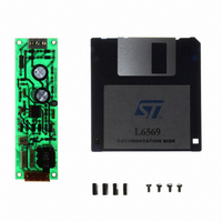
APPENDIX A: CFL DEMONSTRATION BOARD WITH THE L6569 A demonstration board was developed as an ex- ample for Compact Fluorescent Lamp ballast optimised for a CF18DT/E/830 18W lamp from Osram-Sylvania. Using the L6569 the circuit achieves preheat, ignition ...
Page 12
AN880 APPLICATION NOTE Figure 24: PCB Layout of the board. Figure 25: PCB component placement diagram. The resonant choke The inductance of the choke is 2.4 mH with a minimum saturation current of 0. the prac- tical example ...
Page 13
APPENDIX B: Rating of the capacitive supply with the L6569 driver The supply is made with the snubber and a start up resistor snubber circuit is used to minimize the MOS- FETs dissipation. It also achieves ...
Page 14
... STMicroelectronics. Specification mentioned in this publication are subject to change without notice. This publication supersedes and replaces all information previously supplied. STMicroelectronics products are not authorized for use as critical components in life support devices or systems without express written approval of STMicroelectronics. The ST logo is a registered trademark of STMicroelectronics © ...