EVAL6569 STMicroelectronics, EVAL6569 Datasheet - Page 13
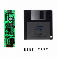
EVAL6569
Manufacturer Part Number
EVAL6569
Description
BOARD EVAL LIGHTING L6569
Manufacturer
STMicroelectronics
Type
Charge Pumpsr
Datasheet
1.EVAL6569.pdf
(14 pages)
Specifications of EVAL6569
Mfg Application Notes
L6569, AN880 App Note
Main Purpose
Lighting, Ballast Control
Embedded
No
Utilized Ic / Part
L6569
Primary Attributes
18 W, Optimized for a CF18DT/E/830, 120 or 230 VAC
Secondary Attributes
Preheating Done with a PTC
Input Voltage
230 V
Product
Power Management Modules
Supply Current
0.17 A
Lead Free Status / RoHS Status
Lead free / RoHS Compliant
For Use With/related Products
L6569
Other names
497-4738


APPENDIX B: Rating of the capacitive supply
with the L6569 driver
The supply is made with the snubber and a start
up resistor R
A snubber circuit is used to minimize the MOS-
FETs dissipation. It also achieves a non dissipa-
tive supply as shown on figure 10.
The MOSFETs gate charge, the driver consump-
tion, the oscillator, and the shunt regulator, define
the circuit consumption.
current is I
Where Q
When V
driver is only consuming. Its current must be mini-
mal to reduce the dissipation of the resistor R
The L6569 has a 150 A start up current, and the
maximum resistance is 2M for a 230Vac line ap-
plication.
We can also reduce the resistor value to get a
faster start up time T
Where C
line voltage.
When the timer oscillates, the capacitor C sup-
S
I
V
R
I
= 2 Q
QS
REG
I
SAV
G
S
F
is lower than the UVLO threshold U
S
S AV
supply voltage
the supply voltage
the MOSFET gate charge
the oscillator resistor and V
the driver supply current
is the supply capacitor, and V
the shunt regulator current.
S
> 2 I
.
:
G
T
S
fsw + I
G
R
+ I
S
S
.
QS
QS
C
V
S
+ I
DC
We can estimate this
+
OSC
U
R
UVLO
V
F
S
+ I
2
REG
+ I
S
REG
the driver
=
UVLO
DC
, the
the
S
.
plies the lamp current during the lower MOS turn
off. To avoid any cross conduction its capacitance
is limited by the driver dead time T
26). Hence the capacitive supply current I
limited.
Where I
switching frequency.
For a ballast such as a CFL one this circuit sup-
plies easily the required current. For instance with
a CF18DT lamp ( I
1nF on 120Vac line, 470 pF on 230 Vac line. At
50 kHz the average capacitive current is 6 mA in
both cases.
Figure 26: Cross conduction of the snubber
GND
GND
GND
I
L
CAV
200 ns/dv ; 50 V/dv ; 0.1 A/dv
is the peak lamp current, and F
capacitor with the upper MOSFET:
capacitor current and voltage
waveforms.
= C V
AN880 APPLICATION NOTE
T
D
DC
C
L
> 230 mA) the capacitor is
F
T
V
SW
D
DC
< I
I
L
L
T
D
D
V
I
RF
C
F
(see figure
HVG
SW
C
+ V
SW
is also
13/14
OUT
the
Related parts for EVAL6569
Image
Part Number
Description
Manufacturer
Datasheet
Request
R

Part Number:
Description:
STMicroelectronics [RIPPLE-CARRY BINARY COUNTER/DIVIDERS]
Manufacturer:
STMicroelectronics
Datasheet:
Part Number:
Description:
STMicroelectronics [LIQUID-CRYSTAL DISPLAY DRIVERS]
Manufacturer:
STMicroelectronics
Datasheet:

Part Number:
Description:
BOARD EVAL FOR MEMS SENSORS
Manufacturer:
STMicroelectronics
Datasheet:
Part Number:
Description:
NPN TRANSISTOR POWER MODULE
Manufacturer:
STMicroelectronics
Datasheet:
Part Number:
Description:
TURBOSWITCH ULTRA-FAST HIGH VOLTAGE DIODE
Manufacturer:
STMicroelectronics
Datasheet:
Part Number:
Description:
Manufacturer:
STMicroelectronics
Datasheet:
Part Number:
Description:
DIODE / SCR MODULE
Manufacturer:
STMicroelectronics
Datasheet:
Part Number:
Description:
DIODE / SCR MODULE
Manufacturer:
STMicroelectronics
Datasheet:
Part Number:
Description:
Search -----> STE16N100
Manufacturer:
STMicroelectronics
Datasheet:
Part Number:
Description:
Search ---> STE53NA50
Manufacturer:
STMicroelectronics
Datasheet:
Part Number:
Description:
NPN Transistor Power Module
Manufacturer:
STMicroelectronics
Datasheet:
Part Number:
Description:
DIODE / SCR MODULE
Manufacturer:
STMicroelectronics
Datasheet: