EVAL5985 STMicroelectronics, EVAL5985 Datasheet - Page 12
EVAL5985
Manufacturer Part Number
EVAL5985
Description
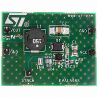
BOARD EVAL FOR L5985
Manufacturer
STMicroelectronics
Type
DC/DC Switching Converters, Regulators & Controllersr
Specifications of EVAL5985
Main Purpose
DC/DC, Step Down
Outputs And Type
1, Non-Isolated
Voltage - Output
3.3V
Current - Output
2A
Voltage - Input
3.3 ~ 18V
Regulator Topology
Buck
Frequency - Switching
500kHz
Board Type
Fully Populated
Utilized Ic / Part
L5985
Input Voltage
2.9 V to 18 V
Output Voltage
0.6 V to 16 V
Product
Power Management Modules
Silicon Manufacturer
ST Micro
Silicon Core Number
L5985
Kit Application Type
Power Management - Voltage Regulator
Application Sub Type
Step Down Switching Regulator
Kit Contents
Board
Lead Free Status / RoHS Status
Lead free / RoHS Compliant
Power - Output
-
Lead Free Status / Rohs Status
Lead free / RoHS Compliant
For Use With/related Products
L5985
Other names
497-6387
EVAL5985
EVAL5985
Available stocks
Company
Part Number
Manufacturer
Quantity
Price


Functional description
4.4
12/37
Over-current protection
The L5985 implements the over current protection sensing current flowing through the
power MOSFET. Due to the noise created by the switching activity of the power MOSFET,
the current sensing is disabled during the initial phase of the conduction time. This avoids an
erroneous detection of a fault condition. This interval is generally known as “masking time”
or “blanking time”. The masking time is about 200 ns.
When the over current is detected, two different behaviors are possible depending on the
operating condition.
1.
2.
So the over current protection can be summarized as an “hiccup” intervention when the
output is in regulation and a constant current during the soft-start phase.
If the output is shorted to ground when the output voltage is on regulation, the over current is
triggered and the device starts cycling with a period of 2048 clock cycles between “hiccup”
(power MOSFET off and no current to the load) and “constant current” with very short on-
time and with reduced switching frequency (up to one eighth of normal switching frequency).
See
Figure 32
Output voltage in regulation. When the over current is sensed, the power MOSFET is
switched off and the internal reference (V
error amplifier, is set to zero and kept in this condition for a soft-start time (T
clock cycles). After this time, a new soft-start phase takes place and the internal
reference begins ramping (see
Soft-start phase. If the over current limit is reached the power MOSFET is turned off
implementing the pulse by pulse over current protection. During the soft-start phase,
under over current condition, the device can skip pulses in order to keep the output
current constant and equal to the current limit. If at the end of the “masking time” the
current is higher than the over current threshold, the power MOSFET is turned off and it
will skip one pulse. If, at the next switching on at the end of the “masking time” the
current is still higher than the threshold, the device will skip two pulses. This
mechanism is repeated and the device can skip up to seven pulses. While, if at the end
of the “masking time” the current is lower than the over current threshold, the number of
skipped cycles is decreased of one unit. At the end of soft-start phase the output
voltage is in regulation and if the over current persists the behavior explained above
takes place. (see
for short circuit behavior.
Figure
8.b)
Doc ID 13006 Rev 5
Figure
8.a).
REF
), that biases the non-inverting input of the
SS
, 2048
L5985
Related parts for EVAL5985
Image
Part Number
Description
Manufacturer
Datasheet
Request
R

Part Number:
Description:
STMicroelectronics [RIPPLE-CARRY BINARY COUNTER/DIVIDERS]
Manufacturer:
STMicroelectronics
Datasheet:
Part Number:
Description:
STMicroelectronics [LIQUID-CRYSTAL DISPLAY DRIVERS]
Manufacturer:
STMicroelectronics
Datasheet:

Part Number:
Description:
BOARD EVAL FOR MEMS SENSORS
Manufacturer:
STMicroelectronics
Datasheet:
Part Number:
Description:
NPN TRANSISTOR POWER MODULE
Manufacturer:
STMicroelectronics
Datasheet:
Part Number:
Description:
TURBOSWITCH ULTRA-FAST HIGH VOLTAGE DIODE
Manufacturer:
STMicroelectronics
Datasheet:
Part Number:
Description:
Manufacturer:
STMicroelectronics
Datasheet:
Part Number:
Description:
DIODE / SCR MODULE
Manufacturer:
STMicroelectronics
Datasheet:
Part Number:
Description:
DIODE / SCR MODULE
Manufacturer:
STMicroelectronics
Datasheet:
Part Number:
Description:
Search -----> STE16N100
Manufacturer:
STMicroelectronics
Datasheet:
Part Number:
Description:
Search ---> STE53NA50
Manufacturer:
STMicroelectronics
Datasheet:
Part Number:
Description:
NPN Transistor Power Module
Manufacturer:
STMicroelectronics
Datasheet:
Part Number:
Description:
DIODE / SCR MODULE
Manufacturer:
STMicroelectronics
Datasheet: