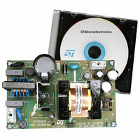
EVALSTSR30-60W STMicroelectronics, EVALSTSR30-60W Datasheet

EVALSTSR30-60W
Specifications of EVALSTSR30-60W
EVALSTSR30-60W
Available stocks
Related parts for EVALSTSR30-60W
EVALSTSR30-60W Summary of contents
Page 1
SUPPLY VOLTAGE RANGE 5.5V TYPICAL PEAK OUTPUT CURRENT: (SOURCE-SINK: 1.5A) OPERATING FREQUENCY 500 KHz INHIBIT BLANKING TIME: 700 ns AUTOMATIC TURN OFF FOR DUTY-CYCLE LESS THAN 14% POSSIBILITY TO OPERATE IN DISCONTINUOUS MODE DESCRIPTION STSR30 Smart ...
Page 2
STSR30 ABSOLUTE MAXIMUM RATINGS (Note 1) Symbol V DC Input Voltage to SGLGND CC OUT Max Gate Drive Output Voltage GATE Max DISABLE Voltage DISABLE Max INHIBIT Voltage (*) INHIBIT CK Clock Input Voltage Range (*) ESD Human Body Model ...
Page 3
PIN DESCRIPTION Pin N° Symbol 1 INHIBIT 2 OUT GATE 3 SGLGND 4 PWRGND DISABLE 7 SETANT 8 CK Name and Function This input enables OUT to work when its voltage is lower than the negative ...
Page 4
STSR30 ELECTRICAL CHARACTERISTICS ( -40 to 125° 100nF ceramic, unless otherwise specified Symbol Parameter SUPPLY INPUT AND UNDER VOLTAGE LOCK OUT V Start Threshold CC Turn OFF Threshold After Start I ...
Page 5
Figure 1 : TIMING DIAGRAM Figure 2 : STSR30 IN FLYBACK CONVERTER SECONDARY SIDE Vi PWM +5V NOTES 1) Ceramic Capacitors C1 and C2 must be placed very close to the IC and R2 set the anticipation time ...
Page 6
STSR30 Figure 3 : STSR30 SYNCHRONIZATION TECHNIQUE The synchronization is based on the revelation of the low level of the drain voltage of the synchronous rectifier. To avoid false triggering of the device during discontinuous mode important that ...
Page 7
Figure 5 : INHIBIT Threshold Voltage vs Temperature Figure Frequency CC Figure 7 : Rise and Fall Time vs Load Capacitor Figure Temperature DS(ON) Figure 9 : Minimum T ON(GATE) Figure ...
Page 8
STSR30 DIM. MIN. A 1.35 A1 0.10 A2 1.10 B 0.33 C 0.19 D 4. 5.80 h 0.25 L 0.40 k ddd 8/10 SO-8 MECHANICAL DATA mm. TYP MAX. 1.75 0.25 1.65 0.51 0.25 5.00 4.00 ...
Page 9
Tape & Reel SO-8 MECHANICAL DATA mm. DIM. MIN 12 8.1 Bo 5.5 Ko 2.1 Po 3.9 P 7.9 TYP MAX. MIN. 330 13.2 0.504 0.795 2.362 22.4 8.5 0.319 5.9 0.216 ...
Page 10
... No license is granted by implication or otherwise under any patent or patent rights of STMicroelectronics. Specifications mentioned in this publication are subject to change without notice. This publication supersedes and replaces all information previously supplied ...


