EVALSTSR30-60W STMicroelectronics, EVALSTSR30-60W Datasheet - Page 3
EVALSTSR30-60W
Manufacturer Part Number
EVALSTSR30-60W
Description
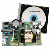
BOARD EVAL USING L6668 & STSR30
Manufacturer
STMicroelectronics
Type
AC/DC Switching Convertersr
Specifications of EVALSTSR30-60W
Mfg Application Notes
EVALSTSR30-60W AppNote
Main Purpose
AC/DC, Primary and Secondary Side
Outputs And Type
1, Isolated
Power - Output
60W
Voltage - Output
12V
Current - Output
5A
Voltage - Input
88 ~ 264VAC
Regulator Topology
Flyback
Frequency - Switching
68kHz
Board Type
Fully Populated
Utilized Ic / Part
L6668, STSR30
Input Voltage
88 V to 264 V
Output Voltage
12 V
Dimensions
120 mm x 75 mm
Product
Power Management Modules
Silicon Manufacturer
ST Micro
Silicon Core Number
L6668 And STSR30
Kit Application Type
Power Management - Voltage Regulator
Application Sub Type
SMPS
Kit Contents
Board
Lead Free Status / RoHS Status
Lead free / RoHS Compliant
For Use With/related Products
L6668, STSR30
Other names
497-6389
EVALSTSR30-60W
EVALSTSR30-60W
Available stocks
Company
Part Number
Manufacturer
Quantity
Price


PIN DESCRIPTION
Pin N°
1
2
3
4
5
6
7
8
PWRGND
OUT
SGLGND
DISABLE
SETANT
Symbol
INHIBIT
V
CK
CC
GATE
This input enables OUT
threshold voltage (V
minimum conduction time (t
possible to turn off the synchronous MOSFET when the current through it tends to
reverse, allowing discontinuous conduction mode and providing protection to the
converter from eventual sinking current from the load.
A blanking time of 700ns allows operation when some voltage ringing is present
during turn-off of primary switch.
Absolute maximum voltage rating of the pin can be exceeded limiting the current
flowing into the pin to 10mA max.
Gate Drive signal for Synchronous MOSFET. Anticipation [t
OUT
Reference for all the control logic signals. This pin is completely separated from
the PWRGND to prevent eventual disturbances to affect the control logic.
Reference for power signals, this pin carries the full peak currents for the output.
The supply voltage range from 4.5V to 5.5V allows applications with logic gate
threshold mosfets. UVLO feature guarantees proper start-up while it avoids
undesirable driving during eventual dropping of the supply voltage.
This pin allows turning off the device completely when kept to low level. In this
condition the IC power consumption is strongly reduced. When this pin goes to
high value, OUT
The voltage on this pin sets the anticipation in turning off the OUTGATE. It is
possible to choose among three different anticipation times by discrete
partitioning of the supply voltage [ANT].
This input provides synchronization for IC’s operations, being the transitions
between the two output conditions based on a positive threshold, equal for the
two slopes. A smart internal control logic mechanism using a 15MHz internal
oscillator generates proper anticipation timing at the turn-off of each output. This
feature allows safe turn-off of Synchronous Rectifiers avoiding any eventual
shoot-through situation on secondary side at both transitions. Clock revelation
mechanism makes the operation of STSR30 particularly suitable for flyback
adaptors application allowing correct operation during discontinuous mode.
Absolute maximum positive voltage rating of the pin can be exceeded limiting the
current flowing into the pin to 10mA max.
GATE
is provided when the clock input goes to low level.
GATE
INHIBIT
turns to switching again according to the CK signal.
GATE
<V
ON(GATE)
to work when its voltage is lower than the negative
H
Name and Function
). If V
INHIBIT
). In typical flyback converter application, it is
>V
H
the OUT
GATE
ANT
will be high for a
] in turning off
STSR30
3/10
Related parts for EVALSTSR30-60W
Image
Part Number
Description
Manufacturer
Datasheet
Request
R

Part Number:
Description:
STMicroelectronics [RIPPLE-CARRY BINARY COUNTER/DIVIDERS]
Manufacturer:
STMicroelectronics
Datasheet:
Part Number:
Description:
STMicroelectronics [LIQUID-CRYSTAL DISPLAY DRIVERS]
Manufacturer:
STMicroelectronics
Datasheet:

Part Number:
Description:
BOARD EVAL FOR MEMS SENSORS
Manufacturer:
STMicroelectronics
Datasheet:
Part Number:
Description:
NPN TRANSISTOR POWER MODULE
Manufacturer:
STMicroelectronics
Datasheet:
Part Number:
Description:
TURBOSWITCH ULTRA-FAST HIGH VOLTAGE DIODE
Manufacturer:
STMicroelectronics
Datasheet:
Part Number:
Description:
Manufacturer:
STMicroelectronics
Datasheet:
Part Number:
Description:
DIODE / SCR MODULE
Manufacturer:
STMicroelectronics
Datasheet:
Part Number:
Description:
DIODE / SCR MODULE
Manufacturer:
STMicroelectronics
Datasheet:
Part Number:
Description:
Search -----> STE16N100
Manufacturer:
STMicroelectronics
Datasheet:
Part Number:
Description:
Search ---> STE53NA50
Manufacturer:
STMicroelectronics
Datasheet:
Part Number:
Description:
NPN Transistor Power Module
Manufacturer:
STMicroelectronics
Datasheet:
Part Number:
Description:
DIODE / SCR MODULE
Manufacturer:
STMicroelectronics
Datasheet: