EVALSTSR30-60W STMicroelectronics, EVALSTSR30-60W Datasheet - Page 4
EVALSTSR30-60W
Manufacturer Part Number
EVALSTSR30-60W
Description
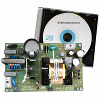
BOARD EVAL USING L6668 & STSR30
Manufacturer
STMicroelectronics
Type
AC/DC Switching Convertersr
Specifications of EVALSTSR30-60W
Mfg Application Notes
EVALSTSR30-60W AppNote
Main Purpose
AC/DC, Primary and Secondary Side
Outputs And Type
1, Isolated
Power - Output
60W
Voltage - Output
12V
Current - Output
5A
Voltage - Input
88 ~ 264VAC
Regulator Topology
Flyback
Frequency - Switching
68kHz
Board Type
Fully Populated
Utilized Ic / Part
L6668, STSR30
Input Voltage
88 V to 264 V
Output Voltage
12 V
Dimensions
120 mm x 75 mm
Product
Power Management Modules
Silicon Manufacturer
ST Micro
Silicon Core Number
L6668 And STSR30
Kit Application Type
Power Management - Voltage Regulator
Application Sub Type
SMPS
Kit Contents
Board
Lead Free Status / RoHS Status
Lead free / RoHS Compliant
For Use With/related Products
L6668, STSR30
Other names
497-6389
EVALSTSR30-60W
EVALSTSR30-60W
Available stocks
Company
Part Number
Manufacturer
Quantity
Price


STSR30
ELECTRICAL CHARACTERISTICS (V
T
Note1: t
Note2: Parameter guaranteed by design
4/10
SUPPLY INPUT AND UNDER VOLTAGE LOCK OUT
GATE DRIVER OUTPUT
TURN-OFF ANTICIPATION TIME
DISABLE
INHIBIT (OUT
SYNCHRONIZATION INPUT
OUT
J
Symbol
R
I
SETANT
D
= -40 to 125°C, C
DS(ON)
I
V
t
V
V
V
V
I
OUT
ANT
V
t
CC
t
t
t
I
OFF
BL
I
CC
DP
DN
HY
CK
R
H
F
P
GATE
I
H
R
is measured between 10% and 90% of the final voltage; t
Start Threshold
Turn OFF Threshold After Start
Unloaded Supply Current
Output Low Voltage
Output High Voltage
Output Source Peak Current
Output Sink Peak Current
Output Series Source Resistance
Output Series Sink Resistance
Rise Time
Fall Time
Clock Propagation Delay to Turn ON
of OUT
OUT
(Fig. 1)
Leakage Current (Note 2)
Positive Threshold Voltage
Negative Threshold Voltage
Hysteresis Voltage
Input Current
Threshold Voltage
Leakage Current
Blanking Time
Rise Threshold Voltage
Fall Threshold Voltage
Duty Cycle Shut Down
Duty Cycle Turn ON after Shut Down
GATE
GATE
GATE
ENABLE)
Turn-off Anticipation Time
1
= C
Parameter
2
= 100nF ceramic, unless otherwise specified.)
CC
= 5V, CK = 100kHz, duty-cycle = 50%, V
OUT
DISABLE = 0V
I
I
T
T
C
C
No Load (Fig. 4)
V
V
V
V
V
T
V
V
V
OUTGATE
OUTGATE
J
J
ANT
ANT
ANT
J
DISABLE
DISABLE
INHIBIT
INHIBIT
INHIBIT
LOAD
LOAD
= 25°C
= 25°C
= 25°C
GATE
= 0 to 1/3V
= 1/3V
= 2/3V
F
= 5nF (Note 1)
= 5nF (Note 1)
is measured between 90% and 10% on the initial voltage
Test Conditions
= +200mV
= -200mV
= +200mV
= 200mA
> V
< V
= -200mA
= no load
CC
CC
DP
DN
to 2/3V
to V
: ON
: OFF
CC
; no load
CC
; no load
CC
; no load
Min.
4.30
-0.1
-0.1
3.3
0.8
-30
0.6
12
INHIBIT
-100
Typ.
0.20
4.65
1.75
150
225
300
700
3.7
3.6
3.2
1.5
1.5
1.7
1.5
0.2
-25
0.8
15
40
40
25
14
19
1
1
= -200mV,
Max.
0.45
2.25
4.5
3.5
0.1
2.4
0.1
1.5
1.2
50
20
4
Unit
mA
mV
µA
µA
nA
ns
ns
ns
ns
ns
%
V
V
A
V
V
V
V
A
A
Related parts for EVALSTSR30-60W
Image
Part Number
Description
Manufacturer
Datasheet
Request
R

Part Number:
Description:
STMicroelectronics [RIPPLE-CARRY BINARY COUNTER/DIVIDERS]
Manufacturer:
STMicroelectronics
Datasheet:
Part Number:
Description:
STMicroelectronics [LIQUID-CRYSTAL DISPLAY DRIVERS]
Manufacturer:
STMicroelectronics
Datasheet:

Part Number:
Description:
BOARD EVAL FOR MEMS SENSORS
Manufacturer:
STMicroelectronics
Datasheet:
Part Number:
Description:
NPN TRANSISTOR POWER MODULE
Manufacturer:
STMicroelectronics
Datasheet:
Part Number:
Description:
TURBOSWITCH ULTRA-FAST HIGH VOLTAGE DIODE
Manufacturer:
STMicroelectronics
Datasheet:
Part Number:
Description:
Manufacturer:
STMicroelectronics
Datasheet:
Part Number:
Description:
DIODE / SCR MODULE
Manufacturer:
STMicroelectronics
Datasheet:
Part Number:
Description:
DIODE / SCR MODULE
Manufacturer:
STMicroelectronics
Datasheet:
Part Number:
Description:
Search -----> STE16N100
Manufacturer:
STMicroelectronics
Datasheet:
Part Number:
Description:
Search ---> STE53NA50
Manufacturer:
STMicroelectronics
Datasheet:
Part Number:
Description:
NPN Transistor Power Module
Manufacturer:
STMicroelectronics
Datasheet:
Part Number:
Description:
DIODE / SCR MODULE
Manufacturer:
STMicroelectronics
Datasheet: