EVALSTSR30-60W STMicroelectronics, EVALSTSR30-60W Datasheet - Page 13
EVALSTSR30-60W
Manufacturer Part Number
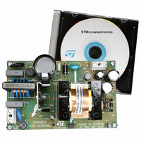
EVALSTSR30-60W
Description
BOARD EVAL USING L6668 & STSR30
Manufacturer
STMicroelectronics
Type
AC/DC Switching Convertersr
Specifications of EVALSTSR30-60W
Mfg Application Notes
EVALSTSR30-60W AppNote
Main Purpose
AC/DC, Primary and Secondary Side
Outputs And Type
1, Isolated
Power - Output
60W
Voltage - Output
12V
Current - Output
5A
Voltage - Input
88 ~ 264VAC
Regulator Topology
Flyback
Frequency - Switching
68kHz
Board Type
Fully Populated
Utilized Ic / Part
L6668, STSR30
Input Voltage
88 V to 264 V
Output Voltage
12 V
Dimensions
120 mm x 75 mm
Product
Power Management Modules
Silicon Manufacturer
ST Micro
Silicon Core Number
L6668 And STSR30
Kit Application Type
Power Management - Voltage Regulator
Application Sub Type
SMPS
Kit Contents
Board
Lead Free Status / RoHS Status
Lead free / RoHS Compliant
For Use With/related Products
L6668, STSR30
Other names
497-6389
EVALSTSR30-60W
EVALSTSR30-60W
Available stocks
Company
Part Number
Manufacturer
Quantity
Price


With reference to the timing diagram of figure 36, when power is first applied to the converter the voltage
on the bulk capacitor (Vin) builds up and, as it reaches about 80V, the HV generator is enabled to oper-
ate (HV_EN is pulled high) so that it draws about 1 mA. This current, diminished by the IC consumption,
charges the bypass capacitor connected between pin Vcc (5) and ground and makes its voltage rise al-
most linearly.
Figure 36. Timing diagram: normal power-up and power-down sequences
As the Vcc voltage reaches the start-up threshold (13.5V typ.) the low-voltage chip starts operating and
the HV generator is cut off by the Vcc_OK signal asserted high. The IC is powered by the energy stored
in the Vcc capacitor until the self-supply circuit (typically an auxiliary winding of the transformer and a
steering diode) develops a voltage high enough to sustain the operation.
The residual consumption of this circuit is just the one on the 15M Ω resistor ( ≈ 10 mW at 400 Vdc), typically
50-70 times lower, under the same conditions, as compared to a standard start-up circuit made with an
external dropping resistor.
Figure 37. Timing diagram showing short-circuit behavior
Vcc restart
Vcc restart
V HVstart
V HVstart
Vcc OFF
Vcc OFF
Vcc_OK
Vcc_OK
Vcc ON
Vcc ON
HV_EN
HV_EN
OUT
OUT
1 mA
1 mA
Vcc
Vcc
Vin
Vin
I HV
I HV
Vcc_OK
Vcc_OK
Vcc
Vcc
Vcc
Vcc
Vcc
Vcc
OUT
OUT
1 mA
1 mA
Vcc
Vcc
I
I
OFF
OFF
HV
HV
rest
rest
ON
ON
Power-up
Power-up
Short circuit occurs here
Short circuit occurs here
operation
operation
Normal
Normal
Power-down
Power-down
regulation is lost here
regulation is lost here
t
t
t
t
t
t
t
t
t
t
t
t
t
t
t
t
t
t
t
t
L6668
13/23
Related parts for EVALSTSR30-60W
Image
Part Number
Description
Manufacturer
Datasheet
Request
R

Part Number:
Description:
STMicroelectronics [RIPPLE-CARRY BINARY COUNTER/DIVIDERS]
Manufacturer:
STMicroelectronics
Datasheet:
Part Number:
Description:
STMicroelectronics [LIQUID-CRYSTAL DISPLAY DRIVERS]
Manufacturer:
STMicroelectronics
Datasheet:

Part Number:
Description:
BOARD EVAL FOR MEMS SENSORS
Manufacturer:
STMicroelectronics
Datasheet:
Part Number:
Description:
NPN TRANSISTOR POWER MODULE
Manufacturer:
STMicroelectronics
Datasheet:
Part Number:
Description:
TURBOSWITCH ULTRA-FAST HIGH VOLTAGE DIODE
Manufacturer:
STMicroelectronics
Datasheet:
Part Number:
Description:
Manufacturer:
STMicroelectronics
Datasheet:
Part Number:
Description:
DIODE / SCR MODULE
Manufacturer:
STMicroelectronics
Datasheet:
Part Number:
Description:
DIODE / SCR MODULE
Manufacturer:
STMicroelectronics
Datasheet:
Part Number:
Description:
Search -----> STE16N100
Manufacturer:
STMicroelectronics
Datasheet:
Part Number:
Description:
Search ---> STE53NA50
Manufacturer:
STMicroelectronics
Datasheet:
Part Number:
Description:
NPN Transistor Power Module
Manufacturer:
STMicroelectronics
Datasheet:
Part Number:
Description:
DIODE / SCR MODULE
Manufacturer:
STMicroelectronics
Datasheet: