EVALSTSR30-60W STMicroelectronics, EVALSTSR30-60W Datasheet - Page 15
EVALSTSR30-60W
Manufacturer Part Number
EVALSTSR30-60W
Description
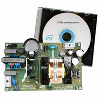
BOARD EVAL USING L6668 & STSR30
Manufacturer
STMicroelectronics
Type
AC/DC Switching Convertersr
Specifications of EVALSTSR30-60W
Mfg Application Notes
EVALSTSR30-60W AppNote
Main Purpose
AC/DC, Primary and Secondary Side
Outputs And Type
1, Isolated
Power - Output
60W
Voltage - Output
12V
Current - Output
5A
Voltage - Input
88 ~ 264VAC
Regulator Topology
Flyback
Frequency - Switching
68kHz
Board Type
Fully Populated
Utilized Ic / Part
L6668, STSR30
Input Voltage
88 V to 264 V
Output Voltage
12 V
Dimensions
120 mm x 75 mm
Product
Power Management Modules
Silicon Manufacturer
ST Micro
Silicon Core Number
L6668 And STSR30
Kit Application Type
Power Management - Voltage Regulator
Application Sub Type
SMPS
Kit Contents
Board
Lead Free Status / RoHS Status
Lead free / RoHS Compliant
For Use With/related Products
L6668, STSR30
Other names
497-6389
EVALSTSR30-60W
EVALSTSR30-60W
Available stocks
Company
Part Number
Manufacturer
Quantity
Price


Figure 39. Standby function: frequency shift vs. timing resistors (normalized quantities)
The determination of R
mode operation takes place (f
noise-free operation. With the aid of the diagrams in figure 39, which show the relationship between the
frequency shift obtained and the ratio of R
possible to determine R
it intercepts the characteristic corresponding to the voltage set at the pin SKIPADJ (#9). From there, draw
a vertical line: on the horizontal axis it is possible to read the required R
Note that the characteristic for V(SKIPADJ)=1.4V corresponds to the burst-mode operation not used (see
next section). Note also that, for a given V(SKIPADJ), there is both a lower limit to the R
a maximum frequency shift allowed. Not observing these limits will result in erratic behavior.
In applications where the switching frequency needs not be tightly fixed for some specific reason there is
no major drawback to this technique. In case this function is not desired, the STBY pin shall be left open.
4.3 Operation at no load or very light load
When the PWM control voltage at pin COMP falls about 50 mV below a threshold externally programma-
ble via pin 9 (SKIPADJ), the IC is disabled with the MOSFET kept in OFF state and its consumption re-
duced at a very low value to minimize Vcc capacitor discharge. The soft-start capacitor is not discharged.
The control voltage now will increase as a result of the feedback reaction to the energy delivery stop, the
threshold will be exceeded and the IC will restart switching again. In this way the converter will work in
burst-mode with a constant peak current defined by the disable level applied at pin 9. A load decrease will
then cause a frequency reduction, which can go down even to few hundred hertz, thus minimizing all fre-
quency-related losses and maximizing efficiency. This kind of operation is noise-free provided the peak
current, which is user-defined by the bias voltage at pin 9, is very low.
The timing diagram of figure 40 illustrates this kind of operation along with the other ones, showing the
most significant signals.
f
f
f
f
min
min
osc
osc
0.9
0.9
0.8
0.8
0.7
0.7
0.6
0.6
0.5
0.5
0.4
0.4
0.3
0.3
0.2
0.2
1
1
0.
0.
STBY
STBY
. Draw an horizontal line corresponding to the desired f
can be done assuming that the minimum switching frequency before burst-
2.5V
2.5V
min
) is specified. This value will be above the audible range to ensure a
2.2V
2.2V
STBY
2V
2V
1.8V
1.8V
to R
T
for different values of the burst-mode threshold, it is
R
R
R
R
STBY
STBY
1
1
T
T
V(SKIPADJ) = 1.6V
V(SKIPADJ) = 1.6V
V(SKIPADJ) = 1.5V
V(SKIPADJ) = 1.5V
V(SKIPADJ) = 1.4V
V(SKIPADJ) = 1.4V
STBY
/R
T
ratio.
min
/f
osc
STBY
ratio as long as
/R
T
ratio and
L6668
10
10
15/23
Related parts for EVALSTSR30-60W
Image
Part Number
Description
Manufacturer
Datasheet
Request
R

Part Number:
Description:
STMicroelectronics [RIPPLE-CARRY BINARY COUNTER/DIVIDERS]
Manufacturer:
STMicroelectronics
Datasheet:
Part Number:
Description:
STMicroelectronics [LIQUID-CRYSTAL DISPLAY DRIVERS]
Manufacturer:
STMicroelectronics
Datasheet:

Part Number:
Description:
BOARD EVAL FOR MEMS SENSORS
Manufacturer:
STMicroelectronics
Datasheet:
Part Number:
Description:
NPN TRANSISTOR POWER MODULE
Manufacturer:
STMicroelectronics
Datasheet:
Part Number:
Description:
TURBOSWITCH ULTRA-FAST HIGH VOLTAGE DIODE
Manufacturer:
STMicroelectronics
Datasheet:
Part Number:
Description:
Manufacturer:
STMicroelectronics
Datasheet:
Part Number:
Description:
DIODE / SCR MODULE
Manufacturer:
STMicroelectronics
Datasheet:
Part Number:
Description:
DIODE / SCR MODULE
Manufacturer:
STMicroelectronics
Datasheet:
Part Number:
Description:
Search -----> STE16N100
Manufacturer:
STMicroelectronics
Datasheet:
Part Number:
Description:
Search ---> STE53NA50
Manufacturer:
STMicroelectronics
Datasheet:
Part Number:
Description:
NPN Transistor Power Module
Manufacturer:
STMicroelectronics
Datasheet:
Part Number:
Description:
DIODE / SCR MODULE
Manufacturer:
STMicroelectronics
Datasheet: