DEMOACKIT Freescale Semiconductor, DEMOACKIT Datasheet - Page 12
DEMOACKIT
Manufacturer Part Number
DEMOACKIT
Description
KIT DEMO KIT FOR DC9S08A
Manufacturer
Freescale Semiconductor
Series
Flexis™r
Type
MCUr
Specifications of DEMOACKIT
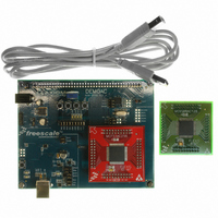
Contents
Board, 2 Daughter Cards, Cable
Processor To Be Evaluated
MCF51AC
Data Bus Width
32 bit
Interface Type
USB
Silicon Manufacturer
Freescale
Core Architecture
Coldfire, HCS08
Core Sub-architecture
Coldfire V1, HCS08
Silicon Core Number
MCF51, MC9S08
Silicon Family Name
Flexis - MCF51AC, Flexis - S08AC
Rohs Compliant
Yes
Tool Type
Demonstration Board
Cpu Core
HCS08
For Use With/related Products
MC9S08AC128, MCF51AC256
For Use With
DEMOACEX - BOARD EXPANSION FOR DEMO KIT
Lead Free Status / RoHS Status
Lead free / RoHS Compliant
Available stocks
Company
Part Number
Manufacturer
Quantity
Price
Company:

Part Number:
DEMOACKIT
Manufacturer:
Freescale Semiconductor
Quantity:
135


D E M O A C
Communications
The DEMOAC board provides 2 UART ports, 1 IIC port, and 1 CAN port. Serial RS-232 com-
munications is support through the integrated BDM. Access to each MCU UART is also avail-
able at connector J1. RS-232 translation is not provided on signals to connector J1.
Virtual COM Port
The serial link through the integrated USB BDM is implemented as a virtual COM port running
through the USB connection. Use of this link require installation of the P&E Micro Demo Board
Toolkit. This toolkit is available on the DVD provided with the DEMOAC.
Refer to the P&E documentation for details and instructions on use of the virtual COM port.
COM_EN
The USB_COM option header individually connects and disconnects the target UART signals
to the integrated USB BDM. Removing a shunt disconnects the associated signal. Installing a
shunt connects the associated signal.
Figure 5: USB_COM Option Header
CAN Port
CAN port signals connect directly between the target MCU and the MCU Port connector at J1.
Refer to the target MCU device Reference Manual for details on using this feature.
IIC Port
IIC port signals connect directly between the target MCU and the MCU Port connector at J1.
Refer to the target MCU device Reference Manual for details on using this feature. Each IIC
signal is pulled up to VDD at the I2C_PULL_EN option header.
NOTE: TGT_TXD and TGT_RXD connect TXD2 and RXD2 lines to the serial input of the inte-
(*) – Default condition
U S E R
grated BDM.
▪
▪
G U I D E
▪
▪
RXD
TXD
Enabled (*)
Enabled (*)
On
12
Shunt
Disabled
Disabled
Off
A P R I L
1 0 ,
2 0 0 8
Related parts for DEMOACKIT
Image
Part Number
Description
Manufacturer
Datasheet
Request
R

Part Number:
Description:
DEM FOR STM8L15X LOW PWR MODES
Manufacturer:
STMicroelectronics
Datasheet:

Part Number:
Description:
Manufacturer:
Freescale Semiconductor, Inc
Datasheet:
Part Number:
Description:
Manufacturer:
Freescale Semiconductor, Inc
Datasheet:
Part Number:
Description:
Manufacturer:
Freescale Semiconductor, Inc
Datasheet:
Part Number:
Description:
Manufacturer:
Freescale Semiconductor, Inc
Datasheet:
Part Number:
Description:
Manufacturer:
Freescale Semiconductor, Inc
Datasheet:
Part Number:
Description:
Manufacturer:
Freescale Semiconductor, Inc
Datasheet:
Part Number:
Description:
Manufacturer:
Freescale Semiconductor, Inc
Datasheet:
Part Number:
Description:
Manufacturer:
Freescale Semiconductor, Inc
Datasheet:
Part Number:
Description:
Manufacturer:
Freescale Semiconductor, Inc
Datasheet:
Part Number:
Description:
Manufacturer:
Freescale Semiconductor, Inc
Datasheet:
Part Number:
Description:
Manufacturer:
Freescale Semiconductor, Inc
Datasheet:
Part Number:
Description:
Manufacturer:
Freescale Semiconductor, Inc
Datasheet:
Part Number:
Description:
Manufacturer:
Freescale Semiconductor, Inc
Datasheet:
Part Number:
Description:
Manufacturer:
Freescale Semiconductor, Inc
Datasheet: