FS2003(US) Equinox Technologies, FS2003(US) Datasheet - Page 65
FS2003(US)
Manufacturer Part Number
FS2003(US)
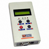
Description
PROGRAMMER PORTABLE HI-SPEED ISP
Manufacturer
Equinox Technologies
Series
FS2003r
Type
Portable Production ISPr
Datasheet
1.FS2003US.pdf
(78 pages)
Specifications of FS2003(US)
Mfg Application Notes
ASCII Text Control Protocol Appl Note
Contents
Programmer, Power Supply Adapter, Software, Cables and Documentation
For Use With/related Products
Atmel/NXP 8051 MCUs and Atmel AVR MCUs
Other names
483-1003


This connection method is suitable for interfacing the programmer to a Target System which features
the following:
The 6-way IDC box header is the most compact header i.e. takes up least space on the Target
System and so is very popular for designs where PCB space is limited. Unfortunately, this connection
method does not have any pins spare for extra functionality such as the SCK2 Oscillator so it should
only be used if this functionality is not required.
To implement this connection method, simply plug a 6-way ISP cable (not supplied) into the
Programmer ISP Header J3 and plug the other end of the cable into the matching header on the
Target System.
Pin
No
1
2
3
4
62
4.4 J3 - Atmel 6-way ISP Header (SPI Interface)
•
•
Programmer
Pin name
PROG_MISO
PROG_VCC
PROG_SCK1
PROG_MOSI
Atmel 6-way IDC ISP Header
An Atmel device which features the 3-wire SPI + RESET Programming Interface
Programmer
Input /
Output
I
P
O
O
Connect to
pin on
Target Device
MISO
(except for
ATmega103/128/64
– connect to TXD
pin instead)
TARGET_VCC
SCK
MOSI
(except for
ATmega103/128/64
– connect to RXD
pin instead)
Figure 4.4.1 - Atmel 6-way IDC Header (J3) viewed from above
Warning!
Connecting to the wrong ISP Header may cause catastrophic
damage to the Programmer & Target System
FS2003 ISP Programmer - User Guide V1.08 – 1
Description
Master In Slave Out
This is the SPI data input pin to the
programmer. This pin should be
connected to the MISO pin on the Target
Microcontroller.
Target Vcc
This pin should be connected to the
Target System Vcc. This voltage could be
used to power the programmer depending
on the settings of the power switch/jumper
on the programmer.
SPI Serial Clock Output
This is the SPI clock output signal.
Master Out Slave In
This is the SPI data output pin from the
programmer. This pin should be
connected to the MOSI pin on the Target
Microcontroller.
st
August 2008
Related parts for FS2003(US)
Image
Part Number
Description
Manufacturer
Datasheet
Request
R

Part Number:
Description:
U[GRADE FS2003 ATC SERIAL CONTRO
Manufacturer:
Equinox Technologies

Part Number:
Description:
UPGRADE FS2003 JTAG ISP AVR MCU
Manufacturer:
Equinox Technologies
Datasheet:
Part Number:
Description:
UPGRADE FS2003 ATMEL AT91SAM7
Manufacturer:
Equinox Technologies
Datasheet:

Part Number:
Description:
PROGRAMMER, ISP
Manufacturer:
Equinox Technologies
Datasheet:

Part Number:
Description:
TRANSF 10VAC .24A SPLIT PACK
Manufacturer:
Triad Magnetics
Datasheet:

Part Number:
Description:
TRANSF 10VAC .6A SPLIT PACK
Manufacturer:
Triad Magnetics
Datasheet:

Part Number:
Description:
TRANSF 10VAC 1.2A SPLIT PACK
Manufacturer:
Triad Magnetics
Datasheet:

Part Number:
Description:
TRANSF 10VAC .11A SPLIT PACK
Manufacturer:
Triad Magnetics
Datasheet:

Part Number:
Description:
RES 10 OHM 20W 5% SILICONE PCB
Manufacturer:
Huntington Electric Inc.
Datasheet:
Part Number:
Description:
RES .50 OHM 20W 5% SILICONE PCB
Manufacturer:
Huntington Electric Inc.
Datasheet:
Part Number:
Description:
RES 1.0 OHM 20W 5% SILICONE PCB
Manufacturer:
Huntington Electric Inc.
Datasheet:
Part Number:
Description:
RES 5.0 OHM 20W 5% SILICONE PCB
Manufacturer:
Huntington Electric Inc.
Datasheet:
Part Number:
Description:
RES 25 OHM 20W 5% SILICONE PCB
Manufacturer:
Huntington Electric Inc.
Datasheet:
Part Number:
Description:
RES 2.5K OHM 20W 5% SILICON PCB
Manufacturer:
Huntington Electric Inc.
Datasheet:
Part Number:
Description:
RES 250 OHM 20W 5% SILICONE PCB
Manufacturer:
Huntington Electric Inc.
Datasheet: