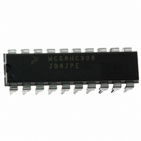
MC68HC908JB8JPE Freescale Semiconductor, MC68HC908JB8JPE Datasheet - Page 132

MC68HC908JB8JPE
Manufacturer Part Number
MC68HC908JB8JPE
Description
IC MCU FLASH 8BIT 8K 20-DIP
Manufacturer
Freescale Semiconductor
Series
HC08r
Datasheet
1.MC908JB8JDWE.pdf
(286 pages)
Specifications of MC68HC908JB8JPE
Core Processor
HC08
Core Size
8-Bit
Speed
3MHz
Connectivity
USB
Peripherals
LVD, POR, PWM
Number Of I /o
13
Program Memory Size
8KB (8K x 8)
Program Memory Type
FLASH
Ram Size
256 x 8
Voltage - Supply (vcc/vdd)
4 V ~ 5.5 V
Oscillator Type
Internal
Operating Temperature
0°C ~ 70°C
Package / Case
20-DIP (0.300", 7.62mm)
Controller Family/series
HC08
No. Of I/o's
13
Ram Memory Size
256Byte
Cpu Speed
3MHz
No. Of Timers
1
Embedded Interface Type
USB
Rohs Compliant
Yes
Processor Series
HC08JB
Core
HC08
Data Bus Width
8 bit
Data Ram Size
256 B
Interface Type
USB
Maximum Clock Frequency
3 MHz
Number Of Programmable I/os
37
Number Of Timers
2
Operating Supply Voltage
4 V to 5.5 V
Maximum Operating Temperature
+ 70 C
Mounting Style
Through Hole
Development Tools By Supplier
FSICEBASE, DEMO908GZ60E, M68EML08GZE, KITUSBSPIDGLEVME, KITUSBSPIEVME, KIT33810EKEVME
Minimum Operating Temperature
0 C
Lead Free Status / RoHS Status
Lead free / RoHS Compliant
Eeprom Size
-
Data Converters
-
Lead Free Status / Rohs Status
Details
- Current page: 132 of 286
- Download datasheet (2Mb)
Universal Serial Bus Module (USB)
9.5.5 Low-Speed Device
9.6 Clock Requirements
Technical Data
132
Low-speed devices are configured by the position of a pull-up resistor on
the USB D– pin of the MCU. Low-speed devices are terminated as
shown in
For low-speed transmissions, the transmitter’s EOP width must be
between 1.25µs and 1.50µs. These ranges include timing variations due
to differential buffer delay and rise/fall time mismatches and to noise and
other random effects. A low-speed receiver must accept a 670ns SE0
followed by a J transition as a valid EOP. An SE0 shorter than
330ns or an SE0 not followed by a J transition are rejected as an EOP.
Any SE0 that is 8µs or longer is automatically a reset.
The low-speed data rate is nominally 1.5 Mbps. The OSCXCLK signal
driven by the oscillator circuits is the clock source for the USB module
and requires that a 6-MHz oscillator circuit be connected to the OSC1
and OSC2 pins. The permitted frequency tolerance for low-speed
functions is approximately
inaccuracies from all sources: initial frequency accuracy, crystal
capacitive loading, supply voltage on the oscillator, temperature, and
aging. The jitter in the low-speed data rate must be less than 10ns.
Figure 9-9. External Low-Speed Device Configuration
Universal Serial Bus Module (USB)
Figure 9-9
MCU
MC68HC908JB8•MC68HC08JB8•MC68HC08JT8 — Rev. 2.3
with the pull-up on the D– line.
±
1.5% (15,000 ppm). This tolerance includes
V
D+
D–
REG
(3.3V)
1.5 kΩ
USB LOW-SPEED CABLE
Freescale Semiconductor
Related parts for MC68HC908JB8JPE
Image
Part Number
Description
Manufacturer
Datasheet
Request
R
Part Number:
Description:
Manufacturer:
Freescale Semiconductor, Inc
Datasheet:
Part Number:
Description:
Manufacturer:
Freescale Semiconductor, Inc
Datasheet:
Part Number:
Description:
Manufacturer:
Freescale Semiconductor, Inc
Datasheet:
Part Number:
Description:
Manufacturer:
Freescale Semiconductor, Inc
Datasheet:
Part Number:
Description:
Manufacturer:
Freescale Semiconductor, Inc
Datasheet:
Part Number:
Description:
Manufacturer:
Freescale Semiconductor, Inc
Datasheet:
Part Number:
Description:
Manufacturer:
Freescale Semiconductor, Inc
Datasheet:
Part Number:
Description:
Manufacturer:
Freescale Semiconductor, Inc
Datasheet:
Part Number:
Description:
Manufacturer:
Freescale Semiconductor, Inc
Datasheet:
Part Number:
Description:
Manufacturer:
Freescale Semiconductor, Inc
Datasheet:
Part Number:
Description:
Manufacturer:
Freescale Semiconductor, Inc
Datasheet:
Part Number:
Description:
Manufacturer:
Freescale Semiconductor, Inc
Datasheet:
Part Number:
Description:
Manufacturer:
Freescale Semiconductor, Inc
Datasheet:
Part Number:
Description:
Manufacturer:
Freescale Semiconductor, Inc
Datasheet:
Part Number:
Description:
Manufacturer:
Freescale Semiconductor, Inc
Datasheet:


