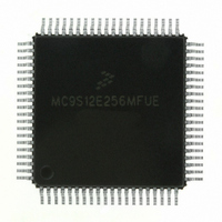
MC9S12E256MFUE Freescale Semiconductor, MC9S12E256MFUE Datasheet - Page 344

MC9S12E256MFUE
Manufacturer Part Number
MC9S12E256MFUE
Description
IC MCU 256K FLASH 25MHZ 80-QFP
Manufacturer
Freescale Semiconductor
Series
HCS12r
Specifications of MC9S12E256MFUE
Core Processor
HCS12
Core Size
16-Bit
Speed
25MHz
Connectivity
EBI/EMI, I²C, SCI, SPI
Peripherals
POR, PWM, WDT
Number Of I /o
60
Program Memory Size
256KB (256K x 8)
Program Memory Type
FLASH
Ram Size
16K x 8
Voltage - Supply (vcc/vdd)
2.35 V ~ 2.75 V
Data Converters
A/D 16x10b; D/A 2x8b
Oscillator Type
Internal
Operating Temperature
-40°C ~ 125°C
Package / Case
80-QFP
Processor Series
S12E
Core
HCS12
Data Bus Width
16 bit
Data Ram Size
16 KB
Interface Type
I2C/SCI/SPI
Maximum Clock Frequency
50 MHz
Number Of Programmable I/os
60
Number Of Timers
12
Operating Supply Voltage
0 V to 5 V
Maximum Operating Temperature
+ 125 C
Mounting Style
SMD/SMT
3rd Party Development Tools
EWHCS12
Minimum Operating Temperature
- 40 C
On-chip Adc
16-ch x 10-bit
On-chip Dac
2-ch x 8-bit
Controller Family/series
HCS12/S12X
No. Of I/o's
60
Ram Memory Size
16KB
Cpu Speed
25MHz
No. Of Timers
3
Embedded Interface Type
I2C, SCI, SPI
Rohs Compliant
Yes
For Use With
M68EVB912E128 - BOARD EVAL FOR MC9S12E128/64
Lead Free Status / RoHS Status
Lead free / RoHS Compliant
Eeprom Size
-
Lead Free Status / Rohs Status
Lead free / RoHS Compliant
Available stocks
Company
Part Number
Manufacturer
Quantity
Price
Company:
Part Number:
MC9S12E256MFUE
Manufacturer:
FREESCAL
Quantity:
329
Company:
Part Number:
MC9S12E256MFUE
Manufacturer:
Freescale Semiconductor
Quantity:
10 000
- Current page: 344 of 602
- Download datasheet (4Mb)
Chapter 11 Pulse Width Modulator with Fault Protection (PMF15B6CV2)
11.3.2.24 PMF Deadtime A Register (PMFDTMA)
Read anytime. This register cannot be modified after the WP bit is set.
11.3.2.25 PMF Enable Control B Register (PMFENCB)
Read anytime and write only if MTG is set.
344
Module Base + 0x0026
Module Base + 0x0028
PMFDTMA
PWMENB
Reset
Reset
Field
Field
11–0
7
W
W
R
R
PWMENB
15
0
0
PMF Deadtime A Bits — The 12-bit value written to this register is the number of PWM clock cycles in
complementary channel operation. A reset sets the PWM deadtime register to a default value of 0x0FFF,
selecting a deadtime of 256-PWM clock cycles minus one bus clock cycle.
Note: Deadtime is affected by changes to the prescaler value. The deadtime duration is determined as follows:
PWM Generator B Enable — If MTG is clear, this bit reads zero and cannot be written.
If MTG is set, this bit when set enables the PWM generator B and the PWM2 and PWM3 pins. When PWMENB
is clear, PWM generator B is disabled, and the PWM2 and PWM3 pins are in their inactive states unless the
OUTCTL2 and OUTCTL3 bits are set.
0 PWM generator B and PWM2–3 pins disabled unless the respective OUTCTL bit is set.
1 PWM generator B and PWM2–3 pins enabled.
0
7
= Unimplemented or Reserved
14
0
0
DT = P
value of dead time. For example: if the prescaler is programmed for a divide-by-two and the PMFDTMA is
set to five, then P = 2 and the deadtime value is equal to DT = 2
case exists when the P = 1, then DT = PMFDTMA.
= Unimplemented or Reserved
13
0
0
Figure 11-31. PMF Enable Control B Register (PMFENCB)
PMFDTMA – 1, where DT is deadtime, P is the prescaler value, PMFDTMA is the programmed
0
0
6
Figure 11-30. PMF Deadtime A Register (PMFDTMA)
12
0
0
Table 11-31. PMFDTMA Field Descriptions
Table 11-32. PMFENCB Field Descriptions
11
1
MC9S12E256 Data Sheet, Rev. 1.08
0
0
5
10
1
1
9
0
0
4
1
8
Description
Description
1
7
3
0
0
PMFDTMA
1
6
1
5
5 – 1 = 9 IPbus clock cycles. A special
0
0
2
4
1
1
3
LDOKB
Freescale Semiconductor
0
1
1
2
PWMRIEB
1
1
0
0
1
0
Related parts for MC9S12E256MFUE
Image
Part Number
Description
Manufacturer
Datasheet
Request
R
Part Number:
Description:
Manufacturer:
Freescale Semiconductor, Inc
Datasheet:
Part Number:
Description:
Manufacturer:
Freescale Semiconductor, Inc
Datasheet:
Part Number:
Description:
Manufacturer:
Freescale Semiconductor, Inc
Datasheet:
Part Number:
Description:
Manufacturer:
Freescale Semiconductor, Inc
Datasheet:
Part Number:
Description:
Manufacturer:
Freescale Semiconductor, Inc
Datasheet:
Part Number:
Description:
Manufacturer:
Freescale Semiconductor, Inc
Datasheet:
Part Number:
Description:
Manufacturer:
Freescale Semiconductor, Inc
Datasheet:
Part Number:
Description:
Manufacturer:
Freescale Semiconductor, Inc
Datasheet:
Part Number:
Description:
Manufacturer:
Freescale Semiconductor, Inc
Datasheet:
Part Number:
Description:
Manufacturer:
Freescale Semiconductor, Inc
Datasheet:
Part Number:
Description:
Manufacturer:
Freescale Semiconductor, Inc
Datasheet:
Part Number:
Description:
Manufacturer:
Freescale Semiconductor, Inc
Datasheet:
Part Number:
Description:
Manufacturer:
Freescale Semiconductor, Inc
Datasheet:
Part Number:
Description:
Manufacturer:
Freescale Semiconductor, Inc
Datasheet:
Part Number:
Description:
Manufacturer:
Freescale Semiconductor, Inc
Datasheet:


