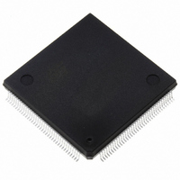
ST10R167-Q3 STMicroelectronics, ST10R167-Q3 Datasheet - Page 9

ST10R167-Q3
Manufacturer Part Number
ST10R167-Q3
Description
IC MCU 16BIT ROMLESS 144-PQFP
Manufacturer
STMicroelectronics
Series
ST10r
Datasheet
1.ST10R167-Q3.pdf
(63 pages)
Specifications of ST10R167-Q3
Core Processor
ST10
Core Size
16-Bit
Speed
25MHz
Connectivity
CAN, EBI/EMI, SSC, UART/USART
Peripherals
POR, PWM, WDT
Number Of I /o
111
Program Memory Type
ROMless
Ram Size
4K x 8
Voltage - Supply (vcc/vdd)
4.5 V ~ 5.5 V
Data Converters
A/D 16x10b
Oscillator Type
Internal
Operating Temperature
-40°C ~ 125°C
Package / Case
144-QFP
Processor Series
ST10R1x
Core
ST10
Data Bus Width
16 bit
Program Memory Size
32 KB
Data Ram Size
4 KB
Interface Type
CAN/SSC/USART
Maximum Clock Frequency
25 MHz
Number Of Programmable I/os
111
Number Of Timers
5
Maximum Operating Temperature
+ 125 C
Mounting Style
SMD/SMT
Minimum Operating Temperature
- 40 C
On-chip Adc
16-ch x 10-bit
Lead Free Status / RoHS Status
Lead free / RoHS Compliant
Eeprom Size
-
Program Memory Size
-
Lead Free Status / Rohs Status
Lead free / RoHS Compliant
Other names
497-2043
Available stocks
Company
Part Number
Manufacturer
Quantity
Price
Company:
Part Number:
ST10R167-Q3
Manufacturer:
ST
Quantity:
556
Company:
Part Number:
ST10R167-Q3
Manufacturer:
STMicroelectronics
Quantity:
10 000
Part Number:
ST10R167-Q3
Manufacturer:
ST
Quantity:
20 000
Company:
Part Number:
ST10R167-Q3/TR
Manufacturer:
STMicroelectronics
Quantity:
10 000
Company:
Part Number:
ST10R167-Q3B0
Manufacturer:
ST
Quantity:
1 343
Part Number:
ST10R167-Q3B0
Manufacturer:
ST
Quantity:
20 000
II - PIN DATA (continued)
Table 1 : Pin list (continued)
RSTOUT
Symbol
V
V
RPD
AGND
V
NMI
V
AREF
DD
SS
17, 46, 56,
72, 82, 93,
18, 45, 55,
71, 83, 94,
109, 126,
110, 127,
136, 144
139, 143
141
142
Pin
37
38
84
Type
O
I
-
-
-
-
-
Internal Reset Indication Output. This pin is set to a low level when the
part is executing either a hardware-, a software- or a watchdog-timer
reset. RSTOUT remains low until the EINIT (end of initialization) instruc-
tion is executed.
Non-Maskable Interrupt Input. A high to low transition at this pin causes
the CPU to vector to the NMI trap routine. If bit PWDCFG = ‘0’ in
SYSCON register, when the PWRDN (power down) instruction is exe-
cuted, the NMI pin must be low in order to force the ST10R167 to go into
power down mode. If NMI is high and PWDCFG =’0’, when PWRDN is
executed, the part will continue to run in normal mode.
If not used, pin NMI should be pulled high externally.
Reference voltage for the A/D converter.
Reference ground for the A/D converter.
This pin is used as the timing pin for the return from powerdown circuit
and power-up asynchronous reset.
Digital Supply Voltage:
= + 5V during normal operation and idle mode.
> + 2.5V during power down mode
Digital Ground.
Function
ST10R167
9/63


