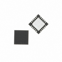
C8051T635-GM Silicon Laboratories Inc, C8051T635-GM Datasheet - Page 4

C8051T635-GM
Manufacturer Part Number
C8051T635-GM
Description
IC MCU 2KB 20PIN QFN
Manufacturer
Silicon Laboratories Inc
Series
C8051T63xr
Specifications of C8051T635-GM
Program Memory Type
OTP
Program Memory Size
2KB (2K x 8)
Package / Case
20-QFN
Core Processor
8051
Core Size
8-Bit
Speed
25MHz
Connectivity
SMBus (2-Wire/I²C), SPI, UART/USART
Peripherals
POR, PWM, WDT
Number Of I /o
17
Ram Size
768 x 8
Voltage - Supply (vcc/vdd)
1.8 V ~ 3.6 V
Oscillator Type
Internal
Operating Temperature
-40°C ~ 85°C
Processor Series
C8051T6x
Core
8051
Data Bus Width
8 bit
Data Ram Size
768 B
Interface Type
I2C/SPI/UART
Maximum Clock Frequency
25 MHz
Number Of Programmable I/os
17
Number Of Timers
4
Operating Supply Voltage
1.8 V to 3.6 V
Maximum Operating Temperature
+ 85 C
Mounting Style
SMD/SMT
3rd Party Development Tools
PK51, CA51, A51, ULINK2
Development Tools By Supplier
C8051T630DK
Minimum Operating Temperature
- 40 C
Package
20QFN EP
Device Core
8051
Family Name
C8051T63x
Maximum Speed
25 MHz
Lead Free Status / RoHS Status
Lead free / RoHS Compliant
For Use With
336-1464 - KIT DEV FOR C8051T630 FAMILY
Eeprom Size
-
Data Converters
-
Lead Free Status / Rohs Status
Lead free / RoHS Compliant
Other names
336-1463-5
Available stocks
Company
Part Number
Manufacturer
Quantity
Price
Company:
Part Number:
C8051T635-GM
Manufacturer:
Silicon
Quantity:
750
C8051T630/1/2/3/4/5
15. Interrupts ................................................................................................................ 80
16. EPROM Memory ..................................................................................................... 89
17. Power Management Modes................................................................................... 92
18. Reset Sources ........................................................................................................ 95
19. Oscillators and Clock Selection ......................................................................... 101
20. Port Input/Output ................................................................................................. 109
4
15.1. MCU Interrupt Sources and Vectors................................................................ 81
15.2. Interrupt Register Descriptions ........................................................................ 82
15.3. INT0 and INT1 External Interrupts................................................................... 87
16.1. Programming and Reading the EPROM Memory ........................................... 89
16.2. Security Options .............................................................................................. 90
16.3. Program Memory CRC .................................................................................... 91
17.1. Idle Mode......................................................................................................... 92
17.2. Stop Mode ....................................................................................................... 93
17.3. Suspend Mode ................................................................................................ 93
18.1. Power-On Reset .............................................................................................. 96
18.2. Power-Fail Reset/VDD Monitor ....................................................................... 97
18.3. External Reset ................................................................................................. 98
18.4. Missing Clock Detector Reset ......................................................................... 98
18.5. Comparator0 Reset ......................................................................................... 99
18.6. PCA Watchdog Timer Reset ........................................................................... 99
18.7. EPROM Error Reset ........................................................................................ 99
18.8. Software Reset ................................................................................................ 99
19.1. System Clock Selection................................................................................. 101
19.2. Programmable Internal High-Frequency (H-F) Oscillator .............................. 103
19.3. Programmable Internal Low-Frequency (L-F) Oscillator ............................... 105
19.4. External Oscillator Drive Circuit..................................................................... 106
20.1. Port I/O Modes of Operation.......................................................................... 110
20.2. Assigning Port I/O Pins to Analog and Digital Functions............................... 112
15.1.1. Interrupt Priorities.................................................................................... 81
15.1.2. Interrupt Latency ..................................................................................... 81
16.1.1. EPROM Write Procedure ........................................................................ 89
16.1.2. EPROM Read Procedure........................................................................ 90
16.3.1. Performing 32-bit CRCs on Full EPROM Content .................................. 91
16.3.2. Performing 16-bit CRCs on 256-Byte EPROM Blocks............................ 91
19.2.1. Internal Oscillator Suspend Mode ......................................................... 103
19.3.1. Calibrating the Internal L-F Oscillator.................................................... 105
19.4.1. External RC Example............................................................................ 108
19.4.2. External Capacitor Example.................................................................. 108
20.1.1. Port Pins Configured for Analog I/O...................................................... 110
20.1.2. Port Pins Configured For Digital I/O...................................................... 110
20.1.3. Interfacing Port I/O to 5V Logic ............................................................. 111
20.2.1. Assigning Port I/O Pins to Analog Functions ........................................ 112
20.2.2. Assigning Port I/O Pins to Digital Functions.......................................... 112
20.2.3. Assigning Port I/O Pins to External Digital Event Capture Functions ... 113
Rev. 1.0


