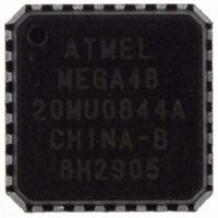
ATMEGA48-20MU Atmel, ATMEGA48-20MU Datasheet - Page 60

ATMEGA48-20MU
Manufacturer Part Number
ATMEGA48-20MU
Description
IC AVR MCU 4K 20MHZ 5V 32-QFN
Manufacturer
Atmel
Series
AVR® ATmegar
Specifications of ATMEGA48-20MU
Core Processor
AVR
Core Size
8-Bit
Speed
20MHz
Connectivity
I²C, SPI, UART/USART
Peripherals
Brown-out Detect/Reset, POR, PWM, WDT
Number Of I /o
23
Program Memory Size
4KB (2K x 16)
Program Memory Type
FLASH
Eeprom Size
256 x 8
Ram Size
512 x 8
Voltage - Supply (vcc/vdd)
2.7 V ~ 5.5 V
Data Converters
A/D 8x10b
Oscillator Type
Internal
Operating Temperature
-40°C ~ 85°C
Package / Case
32-VQFN Exposed Pad, 32-HVQFN, 32-SQFN, 32-DHVQFN
Processor Series
ATMEGA48x
Core
AVR8
Data Bus Width
8 bit
Data Ram Size
512 B
Interface Type
2-Wire/SPI/USART/Serial
Maximum Clock Frequency
20 MHz
Number Of Programmable I/os
23
Number Of Timers
3
Operating Supply Voltage
2.7 V to 5.5 V
Maximum Operating Temperature
+ 85 C
Mounting Style
SMD/SMT
3rd Party Development Tools
EWAVR, EWAVR-BL
Development Tools By Supplier
ATAVRDRAGON, ATSTK500, ATSTK600, ATAVRISP2, ATAVRONEKIT
Minimum Operating Temperature
- 40 C
On-chip Adc
8-ch x 10-bit
Controller Family/series
AVR MEGA
No. Of I/o's
23
Eeprom Memory Size
256Byte
Ram Memory Size
512Byte
Cpu Speed
20MHz
No. Of Timers
3
Rohs Compliant
Yes
Package
32MLF EP
Device Core
AVR
Family Name
ATmega
Maximum Speed
20 MHz
For Use With
ATSTK600-TQFP32 - STK600 SOCKET/ADAPTER 32-TQFPATSTK600-DIP40 - STK600 SOCKET/ADAPTER 40-PDIP770-1007 - ISP 4PORT ATMEL AVR MCU SPI/JTAGATAVRDRAGON - KIT DRAGON 32KB FLASH MEM AVRATAVRISP2 - PROGRAMMER AVR IN SYSTEMATJTAGICE2 - AVR ON-CHIP D-BUG SYSTEM
Lead Free Status / RoHS Status
Lead free / RoHS Compliant
Available stocks
Company
Part Number
Manufacturer
Quantity
Price
Company:
Part Number:
ATMEGA48-20MU
Manufacturer:
ATMEL
Quantity:
18 000
- Current page: 60 of 378
- Download datasheet (8Mb)
11.4
Table 11-4.
60
VectorNo.
10
11
12
13
14
15
16
17
18
19
20
21
22
23
24
25
26
1
2
3
4
5
6
7
8
9
Interrupt Vectors in ATmega168
ATmega48/88/168
Reset and Interrupt Vectors in ATmega168
Address
Program
0x0000
0x000C
0x001C
0x002C
0x0002
0x0004
0x0006
0x0008
0x000A
0x000E
0x0010
0x0012
0x0014
0x0016
0x0018
0x001A
0x001E
0x0020
0x0022
0x0024
0x0026
0x0028
0x002A
0x002E
0x0030
0x0032
(1)
(2)
Notes:
0xC1B
0xC1C
0xC1D
0xC1E
0xC1F
Source
RESET
INT0
INT1
PCINT0
PCINT1
PCINT2
WDT
TIMER2 COMPA
TIMER2 COMPB
TIMER2 OVF
TIMER1 CAPT
TIMER1 COMPA
TIMER1 COMPB
TIMER1 OVF
TIMER0 COMPA
TIMER0 COMPB
TIMER0 OVF
SPI, STC
USART, RX
USART, UDRE
USART, TX
ADC
EE READY
ANALOG COMP
TWI
SPM READY
1. When the BOOTRST Fuse is programmed, the device will jump to the Boot Loader address at
reset, see
ATmega168” on page
“Boot Loader Support – Read-While-Write Self-Programming, ATmega88 and
out
ldi
out
sei
<instr>
Interrupt Definition
External Pin, Power-on Reset, Brown-out Reset and Watchdog System Reset
External Interrupt Request 0
External Interrupt Request 1
Pin Change Interrupt Request 0
Pin Change Interrupt Request 1
Pin Change Interrupt Request 2
Watchdog Time-out Interrupt
Timer/Counter2 Compare Match A
Timer/Counter2 Compare Match B
Timer/Counter2 Overflow
Timer/Counter1 Capture Event
Timer/Counter1 Compare Match A
Timer/Coutner1 Compare Match B
Timer/Counter1 Overflow
Timer/Counter0 Compare Match A
Timer/Counter0 Compare Match B
Timer/Counter0 Overflow
SPI Serial Transfer Complete
USART Rx Complete
USART, Data Register Empty
USART, Tx Complete
ADC Conversion Complete
EEPROM Ready
Analog Comparator
2-wire Serial Interface
Store Program Memory Ready
SPH,r16
r16,low(RAMEND)
SPL,r16
268.
xxx
; Set Stack Pointer to top of RAM
; Enable interrupts
2545S–AVR–07/10
Related parts for ATMEGA48-20MU
Image
Part Number
Description
Manufacturer
Datasheet
Request
R

Part Number:
Description:
IC AVR MCU 4K 5V 20MHZ 32-TQFP
Manufacturer:
Atmel
Datasheet:

Part Number:
Description:
Manufacturer:
Atmel Corporation
Datasheet:

Part Number:
Description:
Manufacturer:
Atmel Corporation
Datasheet:

Part Number:
Description:
IC AVR MCU 4K 20MHZ 5V 32TQFP
Manufacturer:
Atmel
Datasheet:

Part Number:
Description:
IC AVR MCU 4K 20MHZ 5V 28DIP
Manufacturer:
Atmel
Datasheet:

Part Number:
Description:
IC AVR MCU 4K 5V 20MHZ 32-TQFP
Manufacturer:
Atmel
Datasheet:

Part Number:
Description:
IC AVR MCU 4K 5V 20MHZ 32-QFN
Manufacturer:
Atmel
Datasheet:

Part Number:
Description:
IC AVR MCU 4K 5V 20MHZ 32-QFN
Manufacturer:
Atmel
Datasheet:

Part Number:
Description:
IC AVR MCU 4K 5V 20MHZ 28-DIP
Manufacturer:
Atmel
Datasheet:

Part Number:
Description:
IC AVR MCU 4K 5V 20MHZ 28-DIP
Manufacturer:
Atmel
Datasheet:

Part Number:
Description:
IC AVR MCU 4K FLASH 20MHZ 28QFN
Manufacturer:
Atmel
Datasheet:

Part Number:
Description:
MCU AVR 4KB FLASH 20MHZ 32QFN
Manufacturer:
Atmel
Datasheet:


