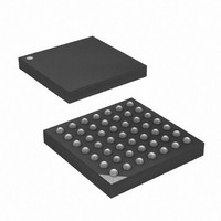
ATXMEGA16A4-CUR Atmel, ATXMEGA16A4-CUR Datasheet - Page 113

ATXMEGA16A4-CUR
Manufacturer Part Number
ATXMEGA16A4-CUR
Description
MCU AVR 16+4KB FLASH 49VFBGA
Manufacturer
Atmel
Series
AVR® XMEGAr
Specifications of ATXMEGA16A4-CUR
Core Processor
AVR
Core Size
8/16-Bit
Speed
32MHz
Connectivity
I²C, IrDA, SPI, UART/USART
Peripherals
Brown-out Detect/Reset, DMA, POR, PWM, WDT
Number Of I /o
34
Program Memory Size
16KB (8K x 16)
Program Memory Type
FLASH
Eeprom Size
1K x 8
Ram Size
2K x 8
Voltage - Supply (vcc/vdd)
1.6 V ~ 3.6 V
Data Converters
A/D 12x12b, D/A 2x12b
Oscillator Type
Internal
Operating Temperature
-40°C ~ 85°C
Package / Case
49-VFBGA
For Use With
ATAVRONEKIT - KIT AVR/AVR32 DEBUGGER/PROGRMMRATSTK600 - DEV KIT FOR AVR/AVR32770-1007 - ISP 4PORT ATMEL AVR MCU SPI/JTAG770-1004 - ISP 4PORT FOR ATMEL AVR MCU SPI
Lead Free Status / RoHS Status
Lead free / RoHS Compliant
Available stocks
Company
Part Number
Manufacturer
Quantity
Price
- Current page: 113 of 445
- Download datasheet (6Mb)
10.3.2
10.4
10.5
10.5.1
10.5.2
Main Power Loss
Main Reset and Start-up Sequence
Battery Backup Brown-Out Detection
Battery Backup enabled
Battery Backup failed and not enabled
The the 32-kHz crystal oscillator, oscillator failure detection and Real Time Counter must be
enabled from software before they can be used.
The Battery Backup Brown-Out Detector (BBBOD) ensures detection of falling power in the Bat-
tery Backup Module before the oscillator stops. When the V
BBBOD threshold voltage, the BOD Flag (BBBODF) will be set.
The BBBOD is sampled from the 1 Hz output of an ultra low power oscillator, and only designed
for detecting slow changes in the V
The BBBOD is turned off when the device runs from the main power. It is enabled when the Bat-
tery Backup Module is switched to be powered from the V
When the main power drops below the programmed BOD threshold voltage, the device will:
1. Switch the Battery Backup Module to be powered from the V
2. Ignore any input signals to the Battery Backup Module.
3. The part of the device that is only powered from V
The Battery Backup System adds some considerations regarding main reset and start-up
sequence. At every start-up after main reset the software should:
1. Check for sufficient power on V
2. Check the Battery Backup Module status by reading the BBPODF and BBBODF flags.
3. Enable access to the Battery Backup Module, by setting the Access Enable (ACCEN) bit.
Based on the status in Battery Backup Module, two different things should be done after the ini-
tial sequence. Each is described in the two sections below.
If BBPODF and/or BBBODF is not set, it indicates that the Battery Backup Modules has not had
any power loss. Then the device should:
1. Set the Access Enable (ACCEN) bit
2. Check for 32-Khz Crystal Oscillator failure by reading the XOSC Failure flag.
If the XOSC Failure flag is cleared no further actions is required.
If the XOSC Failure flag is set, this indicates a failure on the external oscillator in the Battery
Backup Module. The software should assume that the RTC counter value is invalid and take
appropriate action.
If BBPODF and/or BBBODF is set this indicate that voltage on the V
sometime during the period when the rest of the device was unpowererd. The following proce-
dure should be followed:
enabled.
BAT
BAT
pin voltage level.
pin by reading the BBPWR flag.
CC
will be reset.
BAT
pin after a main power BOD.
BAT
BAT
pin voltage drops below the
pin. The BBBOD is
BAT
pin has had a drop
Related parts for ATXMEGA16A4-CUR
Image
Part Number
Description
Manufacturer
Datasheet
Request
R

Part Number:
Description:
DEV KIT FOR AVR/AVR32
Manufacturer:
Atmel
Datasheet:

Part Number:
Description:
INTERVAL AND WIPE/WASH WIPER CONTROL IC WITH DELAY
Manufacturer:
ATMEL Corporation
Datasheet:

Part Number:
Description:
Low-Voltage Voice-Switched IC for Hands-Free Operation
Manufacturer:
ATMEL Corporation
Datasheet:

Part Number:
Description:
MONOLITHIC INTEGRATED FEATUREPHONE CIRCUIT
Manufacturer:
ATMEL Corporation
Datasheet:

Part Number:
Description:
AM-FM Receiver IC U4255BM-M
Manufacturer:
ATMEL Corporation
Datasheet:

Part Number:
Description:
Monolithic Integrated Feature Phone Circuit
Manufacturer:
ATMEL Corporation
Datasheet:

Part Number:
Description:
Multistandard Video-IF and Quasi Parallel Sound Processing
Manufacturer:
ATMEL Corporation
Datasheet:

Part Number:
Description:
High-performance EE PLD
Manufacturer:
ATMEL Corporation
Datasheet:

Part Number:
Description:
8-bit Flash Microcontroller
Manufacturer:
ATMEL Corporation
Datasheet:

Part Number:
Description:
2-Wire Serial EEPROM
Manufacturer:
ATMEL Corporation
Datasheet:


