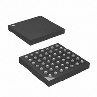
ATXMEGA16A4-CUR Atmel, ATXMEGA16A4-CUR Datasheet - Page 359

ATXMEGA16A4-CUR
Manufacturer Part Number
ATXMEGA16A4-CUR
Description
MCU AVR 16+4KB FLASH 49VFBGA
Manufacturer
Atmel
Series
AVR® XMEGAr
Specifications of ATXMEGA16A4-CUR
Core Processor
AVR
Core Size
8/16-Bit
Speed
32MHz
Connectivity
I²C, IrDA, SPI, UART/USART
Peripherals
Brown-out Detect/Reset, DMA, POR, PWM, WDT
Number Of I /o
34
Program Memory Size
16KB (8K x 16)
Program Memory Type
FLASH
Eeprom Size
1K x 8
Ram Size
2K x 8
Voltage - Supply (vcc/vdd)
1.6 V ~ 3.6 V
Data Converters
A/D 12x12b, D/A 2x12b
Oscillator Type
Internal
Operating Temperature
-40°C ~ 85°C
Package / Case
49-VFBGA
For Use With
ATAVRONEKIT - KIT AVR/AVR32 DEBUGGER/PROGRMMRATSTK600 - DEV KIT FOR AVR/AVR32770-1007 - ISP 4PORT ATMEL AVR MCU SPI/JTAG770-1004 - ISP 4PORT FOR ATMEL AVR MCU SPI
Lead Free Status / RoHS Status
Lead free / RoHS Compliant
Available stocks
Company
Part Number
Manufacturer
Quantity
Price
- Current page: 359 of 445
- Download datasheet (6Mb)
29.7
29.7.1
29.7.2
29.7.3
8077H–AVR–12/09
Register Description - PDI Control and Status Register
STATUS - Program and Debug Interface Status Register
RESET - Program and Debug Interface Reset register
CTRL - Program and Debug Interface Control Register
These register are registers that are accessible in the PDI Control and Status Register Space
(CSRS) using the instructions LDCS and STCS. The CSRS is allocated for registers directly
involved in configuration and status monitoring of the PDI itself.
• Bit 7:2 - Reserved Bits
These bits are reserved and will always be read as zero. For compatibility with future devices,
always write these bits to zero when this register is written.
• Bit 1- NVMEN: Non-Volatile Memory Enable
This status bit is set when the key signalling enables the NVM programming interface. The
External Programmer can poll this bit to verify successful enabling. Writing the NVMEN bit dis-
ables the NVM interface
• Bit 0 - Reserved Bit
This bit is reserved and will always be read as zero. For compatibility with future devices, always
write this bit to zero when this register is written.
• Bit 7:0 - RESET[7:0]: Reset Signature
When the Reset Signature - 0x59 - is written to RESET, the device is forced into reset. The
device is kept in reset until RESET is written with a data value different from the Reset Signature
(0x00 is recommended). Reading the least LSB bit the will return the status of the RESET. The 7
MSB bits will always return the value 0x00 regardless of whether the device is in reset or not.
• Bit 7:3 - Reserved
These bits are unused and reserved for future use. For compatibility with future devices, always
write these bits to zero when this register is written.
Bit
+0x01
Read/Write
Initial Value
Bit
+0x00
Read/Write
Initial Value
Bit
+0x02
Read/Write
Initial Value
R/W
R
R
7
0
7
0
7
0
-
-
R/W
R
R
6
0
6
0
6
0
-
-
R/W
R
R
5
0
5
0
5
0
-
-
R/W
R
R
4
0
4
0
4
0
-
-
RESET[7:0]
R/W
R
R
3
0
3
0
3
0
-
-
R/W
R/W
R
2
0
2
0
2
0
-
GUARDTIME[2:0]
NVMEN
R/W
R/W
R
1
0
1
0
1
0
XMEGA A
R/W
R/W
R
0
0
0
0
0
0
-
STATUS
CTRLB
CTRL
359
Related parts for ATXMEGA16A4-CUR
Image
Part Number
Description
Manufacturer
Datasheet
Request
R

Part Number:
Description:
DEV KIT FOR AVR/AVR32
Manufacturer:
Atmel
Datasheet:

Part Number:
Description:
INTERVAL AND WIPE/WASH WIPER CONTROL IC WITH DELAY
Manufacturer:
ATMEL Corporation
Datasheet:

Part Number:
Description:
Low-Voltage Voice-Switched IC for Hands-Free Operation
Manufacturer:
ATMEL Corporation
Datasheet:

Part Number:
Description:
MONOLITHIC INTEGRATED FEATUREPHONE CIRCUIT
Manufacturer:
ATMEL Corporation
Datasheet:

Part Number:
Description:
AM-FM Receiver IC U4255BM-M
Manufacturer:
ATMEL Corporation
Datasheet:

Part Number:
Description:
Monolithic Integrated Feature Phone Circuit
Manufacturer:
ATMEL Corporation
Datasheet:

Part Number:
Description:
Multistandard Video-IF and Quasi Parallel Sound Processing
Manufacturer:
ATMEL Corporation
Datasheet:

Part Number:
Description:
High-performance EE PLD
Manufacturer:
ATMEL Corporation
Datasheet:

Part Number:
Description:
8-bit Flash Microcontroller
Manufacturer:
ATMEL Corporation
Datasheet:

Part Number:
Description:
2-Wire Serial EEPROM
Manufacturer:
ATMEL Corporation
Datasheet:


