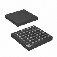
ATXMEGA16A4-CUR Atmel, ATXMEGA16A4-CUR Datasheet - Page 348

ATXMEGA16A4-CUR
Manufacturer Part Number
ATXMEGA16A4-CUR
Description
MCU AVR 16+4KB FLASH 49VFBGA
Manufacturer
Atmel
Series
AVR® XMEGAr
Specifications of ATXMEGA16A4-CUR
Core Processor
AVR
Core Size
8/16-Bit
Speed
32MHz
Connectivity
I²C, IrDA, SPI, UART/USART
Peripherals
Brown-out Detect/Reset, DMA, POR, PWM, WDT
Number Of I /o
34
Program Memory Size
16KB (8K x 16)
Program Memory Type
FLASH
Eeprom Size
1K x 8
Ram Size
2K x 8
Voltage - Supply (vcc/vdd)
1.6 V ~ 3.6 V
Data Converters
A/D 12x12b, D/A 2x12b
Oscillator Type
Internal
Operating Temperature
-40°C ~ 85°C
Package / Case
49-VFBGA
For Use With
ATAVRONEKIT - KIT AVR/AVR32 DEBUGGER/PROGRMMRATSTK600 - DEV KIT FOR AVR/AVR32770-1007 - ISP 4PORT ATMEL AVR MCU SPI/JTAG770-1004 - ISP 4PORT FOR ATMEL AVR MCU SPI
Lead Free Status / RoHS Status
Lead free / RoHS Compliant
Available stocks
Company
Part Number
Manufacturer
Quantity
Price
- Current page: 348 of 445
- Download datasheet (6Mb)
29.3.5
29.3.5.1
8077H–AVR–12/09
Serial Transmission
Drive contention and collision detection
When a data transmission is initiated (by the PDI Controller), the transmitter simply shifts the
start bit, data bits, the parity bit, and the two stop bits out on the PDI_DATA line. The transmis-
sion speed is dictated by the PDI_CLK signal. While in transmission mode, IDLE bits (high bits)
are automatically transmitted to fill possible gaps between successive DATA characters. If a col-
lision is detected during transmission, the output driver is disabled and the interface is put into a
RX mode waiting for a BREAK character.
In order to reduce the effect of a drive contention (the PDI and the programmer drives the
PDI_DATA line at the same time), a mechanism for collision detection is supported. The mecha-
nism is based on the way the PDI drives data out on the PDI_DATA line. As shown in Figure 7,
the output pin driver is only active when the output value changes (from 0-1 or 1-0). Hence, if
two or more successive bit values are the same, the value is only actively driven the first clock
cycle. After this point the output driver is automatically tri-stated, and the PDI_DATA pin has a
bus-keeper responsible for keeping the pin-value unchanged until the output driver is re-enabled
due to a bit value change.
Figure 29-7. Driving data out on the PDI_DATA using bus-keeper
If the programmer and the PDI both drives the PDI_DATA line at the same time, the situation of
drive contention will occur as illustrated in
kept for two or more clock cycles, the PDI is able to verify that the correct bit value is driven on
the PDI_DATA line. If the programmer is driving the PDI_DATA line to the opposite bit value
than what the PDI expects, a collision is detected.
Output enable
Driven output
PDI_CLK
PDI_DATA
1
0
Figure 29-8 on page
1
1
0
349. Every time a bit value is
0
XMEGA A
1
348
Related parts for ATXMEGA16A4-CUR
Image
Part Number
Description
Manufacturer
Datasheet
Request
R

Part Number:
Description:
DEV KIT FOR AVR/AVR32
Manufacturer:
Atmel
Datasheet:

Part Number:
Description:
INTERVAL AND WIPE/WASH WIPER CONTROL IC WITH DELAY
Manufacturer:
ATMEL Corporation
Datasheet:

Part Number:
Description:
Low-Voltage Voice-Switched IC for Hands-Free Operation
Manufacturer:
ATMEL Corporation
Datasheet:

Part Number:
Description:
MONOLITHIC INTEGRATED FEATUREPHONE CIRCUIT
Manufacturer:
ATMEL Corporation
Datasheet:

Part Number:
Description:
AM-FM Receiver IC U4255BM-M
Manufacturer:
ATMEL Corporation
Datasheet:

Part Number:
Description:
Monolithic Integrated Feature Phone Circuit
Manufacturer:
ATMEL Corporation
Datasheet:

Part Number:
Description:
Multistandard Video-IF and Quasi Parallel Sound Processing
Manufacturer:
ATMEL Corporation
Datasheet:

Part Number:
Description:
High-performance EE PLD
Manufacturer:
ATMEL Corporation
Datasheet:

Part Number:
Description:
8-bit Flash Microcontroller
Manufacturer:
ATMEL Corporation
Datasheet:

Part Number:
Description:
2-Wire Serial EEPROM
Manufacturer:
ATMEL Corporation
Datasheet:


