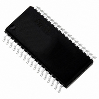
ST72F621L4M1 STMicroelectronics, ST72F621L4M1 Datasheet - Page 44

ST72F621L4M1
Manufacturer Part Number
ST72F621L4M1
Description
IC MCU 8BIT LS 16K 34-SOIC
Manufacturer
STMicroelectronics
Series
ST7r
Datasheet
1.ST72F622L2M1.pdf
(139 pages)
Specifications of ST72F621L4M1
Core Processor
ST7
Core Size
8-Bit
Speed
8MHz
Connectivity
SCI, SPI, USB
Peripherals
DMA, LVD, POR, PWM, WDT
Number Of I /o
23
Program Memory Size
16KB (16K x 8)
Program Memory Type
FLASH
Ram Size
768 x 8
Voltage - Supply (vcc/vdd)
4 V ~ 5.5 V
Data Converters
A/D 8x10b
Oscillator Type
Internal
Operating Temperature
0°C ~ 70°C
Package / Case
34-SOIC (7.5mm Width)
Processor Series
ST72F6x
Core
ST7
Data Bus Width
8 bit
Data Ram Size
768 B
Interface Type
SCI, SPI, USB
Maximum Clock Frequency
12 MHz
Number Of Programmable I/os
23
Number Of Timers
2
Operating Supply Voltage
4 V to 5.5 V
Maximum Operating Temperature
+ 70 C
Mounting Style
SMD/SMT
Minimum Operating Temperature
0 C
On-chip Adc
10 bit
For Use With
497-5046 - KIT TOOL FOR ST7/UPSD/STR7 MCU
Lead Free Status / RoHS Status
Lead free / RoHS Compliant
Eeprom Size
-
Lead Free Status / Rohs Status
In Transition
Other names
497-2112-5
Available stocks
Company
Part Number
Manufacturer
Quantity
Price
Company:
Part Number:
ST72F621L4M1
Manufacturer:
ST
Quantity:
2 272
Company:
Part Number:
ST72F621L4M1
Manufacturer:
ST
Quantity:
5
ST7262xxx
PWM AUTO-RELOAD TIMER (Cont’d)
10.2.2 Functional Description
Counter
The free running 8-bit counter is fed by the output
of the prescaler, and is incremented on every ris-
ing edge of the clock signal.
It is possible to read or write the contents of the
counter on the fly by reading or writing the Counter
Access register (ARTCAR).
When a counter overflow occurs, the counter is
automatically reloaded with the contents of the
ARTARR register (the prescaler is not affected).
Counter clock and prescaler
The counter clock frequency is given by:
The timer counter’s input clock (f
7-bit programmable prescaler, which selects one
of the 8 available taps of the prescaler, as defined
by CC[2:0] bits in the Control/Status Register
(ARTCSR). Thus the division factor of the prescal-
er can be set to 2
This f
the EXCL bit of the ARTCSR register and can be
either the f
The clock input to the counter is enabled by the
TCE (Timer Counter Enable) bit in the ARTCSR
register. When TCE is reset, the counter is
stopped and the prescaler and counter contents
are frozen. When TCE is set, the counter runs at
the rate of the selected clock source.
Figure 32. Output compare control
44/139
COUNTER
f
INPUT
COUNTER
PWMx
PWMDCRx
OCRx
CPU
f
COUNTER
frequency source is selected through
or an external input frequency f
FDh
n
(where n = 0, 1,..7).
= f
INPUT
FEh
/ 2
FDh
ARTARR=FDh
CC[2:0]
INPUT
FFh
FDh
) feeds the
FDh
EXT
.
Doc ID 6996 Rev 5
FEh
Counter and Prescaler Initialization
After RESET, the counter and the prescaler are
cleared and f
The counter can be initialized by:
– Writing to the ARTARR register and then setting
– Writing to the ARTCAR counter access register,
In both cases the 7-bit prescaler is also cleared,
whereupon counting will start from a known value.
Direct access to the prescaler is not possible.
Output compare control
The timer compare function is based on four differ-
ent comparisons with the counter (one for each
PWMx output). Each comparison is made be-
tween the counter value and an output compare
register (OCRx) value. This OCRx register can not
be accessed directly, it is loaded from the duty cy-
cle register (PWMDCRx) at each overflow of the
counter.
This double buffering method avoids glitch gener-
ation when changing the duty cycle on the fly.
the FCRL (Force Counter Re-Load) and the TCE
(Timer Counter Enable) bits in the ARTCSR reg-
ister.
FFh
INPUT
FEh
FDh
= f
CPU
FEh
.
FEh
FFh


