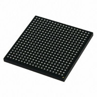
MCIMX251AJM4 Freescale Semiconductor, MCIMX251AJM4 Datasheet - Page 113

MCIMX251AJM4
Manufacturer Part Number
MCIMX251AJM4
Description
IC MPU IMX25 AUTO 400MAPBGA
Manufacturer
Freescale Semiconductor
Series
i.MX25r
Datasheet
1.MCIMX255AJM4.pdf
(140 pages)
Specifications of MCIMX251AJM4
Core Processor
ARM9
Core Size
32-Bit
Speed
400MHz
Connectivity
1-Wire, CAN, EBI/EMI, Ethernet, I²C, MMC, SmartCard, SPI, SSI, UART/USART, USB OTG
Peripherals
DMA, I²S, POR, PWM, WDT
Number Of I /o
128
Program Memory Type
External Program Memory
Ram Size
144K x 8
Voltage - Supply (vcc/vdd)
1.15 V ~ 1.52 V
Data Converters
A/D 3x12b
Oscillator Type
External
Operating Temperature
-40°C ~ 85°C
Package / Case
400-MAPBGA
Lead Free Status / RoHS Status
Lead free / RoHS Compliant
Eeprom Size
-
Program Memory Size
-
Available stocks
Company
Part Number
Manufacturer
Quantity
Price
Company:
Part Number:
MCIMX251AJM4
Manufacturer:
Freescale Semiconductor
Quantity:
10 000
Company:
Part Number:
MCIMX251AJM4A
Manufacturer:
IDT
Quantity:
450
Company:
Part Number:
MCIMX251AJM4A
Manufacturer:
Freescale Semiconductor
Quantity:
135
Company:
Part Number:
MCIMX251AJM4A
Manufacturer:
FREESCALE
Quantity:
648
Company:
Part Number:
MCIMX251AJM4A
Manufacturer:
Freescale Semiconductor
Quantity:
10 000
Part Number:
MCIMX251AJM4A
Manufacturer:
FREESCALE
Quantity:
20 000
assertion of soc is detected. Thus, if the soc signal is continuously asserted, the ADC undergoes successive
conversion cycles and achieves the maximum sampling rate. If soc is negated, no conversion is initiated.
The output data can be read from adcout11...adcout0, and is available tdata nanoseconds after the rising
edge of eoc. The reset signal and the digital signals controlling the analog switches (ypsw, xpsw, ynsw,
xnsw) are totally asynchronous.
The following conditions are necessary to guarantee the correct operation of the ADC:
Freescale Semiconductor
•
•
The input multiplexer selection (selin11…selin0) is stable during both the last clock cycle (14
and the first clock cycle (1
selection during clock cycles 2 to 13.
The references are stable during clock cycle 1 to 13. The best way to guarantee this is to make the
reference multiplexer selection (selrefp and selrefn) before issuing an soc pulse and changing it
only after an eoc pulse has been acquired, during the last clock cycle (14).
i.MX25 Applications Processor for Automotive Products, Rev. 8
st
). The best way to guarantee this is to make the input multiplexer
Figure 82. Start-up Sequence
th
113
)


