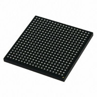
MCIMX251AJM4 Freescale Semiconductor, MCIMX251AJM4 Datasheet - Page 17

MCIMX251AJM4
Manufacturer Part Number
MCIMX251AJM4
Description
IC MPU IMX25 AUTO 400MAPBGA
Manufacturer
Freescale Semiconductor
Series
i.MX25r
Datasheet
1.MCIMX255AJM4.pdf
(140 pages)
Specifications of MCIMX251AJM4
Core Processor
ARM9
Core Size
32-Bit
Speed
400MHz
Connectivity
1-Wire, CAN, EBI/EMI, Ethernet, I²C, MMC, SmartCard, SPI, SSI, UART/USART, USB OTG
Peripherals
DMA, I²S, POR, PWM, WDT
Number Of I /o
128
Program Memory Type
External Program Memory
Ram Size
144K x 8
Voltage - Supply (vcc/vdd)
1.15 V ~ 1.52 V
Data Converters
A/D 3x12b
Oscillator Type
External
Operating Temperature
-40°C ~ 85°C
Package / Case
400-MAPBGA
Lead Free Status / RoHS Status
Lead free / RoHS Compliant
Eeprom Size
-
Program Memory Size
-
Available stocks
Company
Part Number
Manufacturer
Quantity
Price
Company:
Part Number:
MCIMX251AJM4
Manufacturer:
Freescale Semiconductor
Quantity:
10 000
Company:
Part Number:
MCIMX251AJM4A
Manufacturer:
IDT
Quantity:
450
Company:
Part Number:
MCIMX251AJM4A
Manufacturer:
Freescale Semiconductor
Quantity:
135
Company:
Part Number:
MCIMX251AJM4A
Manufacturer:
FREESCALE
Quantity:
648
Company:
Part Number:
MCIMX251AJM4A
Manufacturer:
Freescale Semiconductor
Quantity:
10 000
Part Number:
MCIMX251AJM4A
Manufacturer:
FREESCALE
Quantity:
20 000
Figure 2
powered up. After Core VDD and NVDDx are stable, the analog supplies can be powered up.
3.2.2
There are no special requirements for the power-down sequence. All power supplies can be shut down at
the same time.
3.2.3
In order to guarantee DryIce power-loss protection, which includes that SRTC time is kept during
power-down; in addition to having the proper capacitor placed on the NVCC_DRYICE output pin, users
must follow the specific power-up/down sequence.
For users who want to utilize the DryIce power-loss protection feature, the following power-up sequence
is recommended:
Freescale Semiconductor
QVDD and NVDD
Analog Supplies
1. Assert Power on reset (POR).
2. Turn on NVCC_CRM.
3. At any time from step 2 and to step 4, turn on other digital I/O power suppliers NVCCx.
4. Turn on digital logic domain QVDD no less than 1 ms and no greater than 32 ms after
NVCC_CRM reaches 90 % of 3.3 V. Step 2 and step 4 order are critical for proper power-loss
protection.
shows the power-up sequence diagram. After POR_B is asserted, Core VDD and NVDDx can be
POR_B
Power-Down Sequence
SRTC DryIce Power-Up/Down Sequence
This is to guarantee that POR is stable already at NVCC_CRM/QVDD
power domain interface before QVDD is on, and POR instantly propagates
to QVDD domain after QVDD is on.
i.MX25 Applications Processor for Automotive Products, Rev. 8
Figure 2. Power-Up Sequence Diagram
NOTE
17


