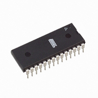
ATMEGA88-20PU Atmel, ATMEGA88-20PU Datasheet - Page 372

ATMEGA88-20PU
Manufacturer Part Number
ATMEGA88-20PU
Description
IC AVR MCU 8K 20MHZ 5V 28DIP
Manufacturer
Atmel
Series
AVR® ATmegar
Specifications of ATMEGA88-20PU
Core Processor
AVR
Core Size
8-Bit
Speed
20MHz
Connectivity
I²C, SPI, UART/USART
Peripherals
Brown-out Detect/Reset, POR, PWM, WDT
Number Of I /o
23
Program Memory Size
8KB (4K x 16)
Program Memory Type
FLASH
Eeprom Size
512 x 8
Ram Size
1K x 8
Voltage - Supply (vcc/vdd)
2.7 V ~ 5.5 V
Data Converters
A/D 6x10b
Oscillator Type
Internal
Operating Temperature
-40°C ~ 85°C
Package / Case
28-DIP (0.300", 7.62mm)
Cpu Family
ATmega
Device Core
AVR
Device Core Size
8b
Frequency (max)
20MHz
Interface Type
SPI/TWI/USART
Total Internal Ram Size
1KB
# I/os (max)
23
Number Of Timers - General Purpose
3
Operating Supply Voltage (typ)
3.3/5V
Operating Supply Voltage (max)
5.5V
Operating Supply Voltage (min)
2.7V
On-chip Adc
6-chx10-bit
Instruction Set Architecture
RISC
Operating Temp Range
-40C to 85C
Operating Temperature Classification
Industrial
Mounting
Through Hole
Pin Count
28
Package Type
PDIP
Processor Series
ATMEGA8x
Core
AVR8
Data Bus Width
8 bit
Data Ram Size
1 KB
Maximum Clock Frequency
20 MHz
Number Of Programmable I/os
23
Number Of Timers
3
Operating Supply Voltage
2.7 V to 5.5 V
Maximum Operating Temperature
+ 85 C
Mounting Style
Through Hole
3rd Party Development Tools
EWAVR, EWAVR-BL
Development Tools By Supplier
ATAVRDRAGON, ATSTK500, ATSTK600, ATAVRISP2, ATAVRONEKIT, ATAVRTS2080A, ATASTK512-EK1-IND
Minimum Operating Temperature
- 40 C
Package
28PDIP
Family Name
ATmega
Maximum Speed
20 MHz
For Use With
ATAVRDRAGON - KIT DRAGON 32KB FLASH MEM AVRATAVRISP2 - PROGRAMMER AVR IN SYSTEM
Lead Free Status / RoHS Status
Lead free / RoHS Compliant
- Current page: 372 of 378
- Download datasheet (8Mb)
18 SPI – Serial Peripheral Interface ......................................................... 160
19 USART0 ................................................................................................. 170
20 USART in SPI Mode ............................................................................. 198
21 2-wire Serial Interface .......................................................................... 208
iv
17.6Compare Match Output Unit ................................................................................143
17.7Modes of Operation .............................................................................................144
17.8Timer/Counter Timing Diagrams .........................................................................148
17.9Asynchronous Operation of Timer/Counter2 .......................................................150
17.10Timer/Counter Prescaler ...................................................................................151
17.11Register Description ..........................................................................................152
18.1Features ..............................................................................................................160
18.2Overview ..............................................................................................................160
18.3SS Pin Functionality ............................................................................................165
18.4Data Modes .........................................................................................................165
18.5Register Description ............................................................................................167
19.1Features ..............................................................................................................170
19.2Overview ..............................................................................................................170
19.3Clock Generation .................................................................................................171
19.4Frame Formats ....................................................................................................174
19.5USART Initialization .............................................................................................176
19.6Data Transmission – The USART Transmitter ....................................................178
19.7Data Reception – The USART Receiver .............................................................180
19.8Asynchronous Data Reception ............................................................................184
19.9Multi-processor Communication Mode ................................................................187
19.10Register Description ..........................................................................................189
19.11Examples of Baud Rate Setting .........................................................................193
20.1Features ..............................................................................................................198
20.2Overview ..............................................................................................................198
20.3Clock Generation .................................................................................................198
20.4SPI Data Modes and Timing ................................................................................199
20.5Frame Formats ....................................................................................................200
20.6Data Transfer .......................................................................................................202
20.7AVR USART MSPIM vs. AVR SPI ......................................................................204
20.8Register Description ............................................................................................205
21.1Features ..............................................................................................................208
ATmega48/88/168
2545S–AVR–07/10
Related parts for ATMEGA88-20PU
Image
Part Number
Description
Manufacturer
Datasheet
Request
R

Part Number:
Description:
IC MCU AVR 8K 5V 20MHZ 32-TQFP
Manufacturer:
Atmel
Datasheet:

Part Number:
Description:
Manufacturer:
Atmel Corporation
Datasheet:

Part Number:
Description:
Manufacturer:
Atmel Corporation
Datasheet:

Part Number:
Description:
MCU AVR 8K FLASH 15MHZ 32-QFN
Manufacturer:
Atmel
Datasheet:

Part Number:
Description:
IC AVR MCU 8K 20MHZ 5V 32TQFP
Manufacturer:
Atmel
Datasheet:

Part Number:
Description:
IC AVR MCU 8K 20MHZ 5V 32-QFN
Manufacturer:
Atmel
Datasheet:

Part Number:
Description:
IC MCU AVR 8K 5V 20MHZ 32-TQFP
Manufacturer:
Atmel
Datasheet:

Part Number:
Description:
IC MCU AVR 8K 5V 20MHZ 32-QFN
Manufacturer:
Atmel
Datasheet:

Part Number:
Description:
IC MCU AVR 8K 5V 20MHZ 32-QFN
Manufacturer:
Atmel
Datasheet:

Part Number:
Description:
IC MCU AVR 8K 5V 20MHZ 28-DIP
Manufacturer:
Atmel
Datasheet:

Part Number:
Description:
IC MCU AVR 8K 5V 20MHZ 28-DIP
Manufacturer:
Atmel
Datasheet:

Part Number:
Description:
MCU AVR 8K FLASH 20MHZ 32TQFP
Manufacturer:
Atmel
Datasheet:

Part Number:
Description:
MCU AVR 8K FLASH 20MHZ 32QFN
Manufacturer:
Atmel
Datasheet:


