Z8F6422AR020SC2104 Zilog, Z8F6422AR020SC2104 Datasheet - Page 128
Z8F6422AR020SC2104
Manufacturer Part Number
Z8F6422AR020SC2104
Description
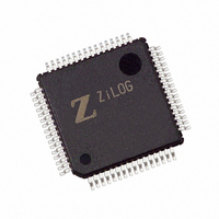
IC ENCORE MCU FLASH 64K 64LQFP
Manufacturer
Zilog
Series
Encore!® XP®r
Specifications of Z8F6422AR020SC2104
Core Processor
Z8
Core Size
8-Bit
Speed
20MHz
Connectivity
I²C, IrDA, SPI, UART/USART
Peripherals
Brown-out Detect/Reset, DMA, POR, PWM, WDT
Number Of I /o
46
Program Memory Size
64KB (64K x 8)
Program Memory Type
FLASH
Ram Size
4K x 8
Voltage - Supply (vcc/vdd)
3 V ~ 3.6 V
Data Converters
A/D 12x10b
Oscillator Type
Internal
Operating Temperature
0°C ~ 70°C
Package / Case
64-LQFP
For Use With
269-4678 - KIT DEV FOR Z8F642 MCU 44 PIN269-4677 - KIT DEV FOR Z8F642 MCU 28PIN269-4540 - KIT DEV FOR Z8 ENCORE 16K TO 64K
Lead Free Status / RoHS Status
Contains lead / RoHS non-compliant
Eeprom Size
-
Other names
269-3641
Available stocks
Company
Part Number
Manufacturer
Quantity
Price


Table 57. UART Control 1 Register (UxCTL1)
PS019921-0308
BITS
FIELD
RESET
R/W
ADDR
MPMD[1]
7
REN—Receive Enable
This bit enables or disables the receiver.
0 = Receiver disabled.
1 = Receiver enabled.
CTSE—CTS Enable
0 = The CTS signal has no effect on the transmitter.
1 = The UART recognizes the CTS signal as an enable control from the transmitter.
PEN—Parity Enable
This bit enables or disables parity. Even or odd is determined by the PSEL bit. It is over-
ridden by the
0 = Parity is disabled.
1 = The transmitter sends data with an additional parity bit and the receiver receives an
additional parity bit.
PSEL—Parity Select
0 = Even parity is transmitted and expected on all received data.
1 = Odd parity is transmitted and expected on all received data.
SBRK—Send Break
This bit pauses or breaks data transmission. Sending a break interrupts any transmission in
progress, so ensure that the transmitter has finished sending data before setting this bit.
0 = No break is sent.
1 = The output of the transmitter is zero.
STOP—Stop Bit Select
0 = The transmitter sends one stop bit.
1 = The transmitter sends two stop bits.
LBEN—Loop Back Enable
0 = Normal operation.
1 = All transmitted data is looped back to the receiver.
MPMD[1:0]—MULTIPROCESSOR Mode
If MULTIPROCESSOR (9-bit) mode is enabled,
00 = The UART generates an interrupt request on all received bytes (data and address).
MPEN
6
MPEN
MPMD[0]
bit.
5
MPBT
F43H and F4BH
4
R/W
0
DEPOL
3
BRGCTL
Z8 Encore! XP
2
Product Specification
RDAIRQ
1
®
F64XX Series
IREN
0
UART
114
Related parts for Z8F6422AR020SC2104
Image
Part Number
Description
Manufacturer
Datasheet
Request
R

Part Number:
Description:
Communication Controllers, ZILOG INTELLIGENT PERIPHERAL CONTROLLER (ZIP)
Manufacturer:
Zilog, Inc.
Datasheet:

Part Number:
Description:
KIT DEV FOR Z8 ENCORE 16K TO 64K
Manufacturer:
Zilog
Datasheet:

Part Number:
Description:
KIT DEV Z8 ENCORE XP 28-PIN
Manufacturer:
Zilog
Datasheet:

Part Number:
Description:
DEV KIT FOR Z8 ENCORE 8K/4K
Manufacturer:
Zilog
Datasheet:

Part Number:
Description:
KIT DEV Z8 ENCORE XP 28-PIN
Manufacturer:
Zilog
Datasheet:

Part Number:
Description:
DEV KIT FOR Z8 ENCORE 4K TO 8K
Manufacturer:
Zilog
Datasheet:
Part Number:
Description:
CMOS Z8 microcontroller. ROM 16 Kbytes, RAM 256 bytes, speed 16 MHz, 32 lines I/O, 3.0V to 5.5V
Manufacturer:
Zilog, Inc.
Datasheet:
Part Number:
Description:
Low-cost microcontroller. 512 bytes ROM, 61 bytes RAM, 8 MHz
Manufacturer:
Zilog, Inc.
Datasheet:
Part Number:
Description:
Z8 4K OTP Microcontroller
Manufacturer:
Zilog, Inc.
Datasheet:
Part Number:
Description:
CMOS SUPER8 ROMLESS MCU
Manufacturer:
Zilog, Inc.
Datasheet:
Part Number:
Description:
SL1866 CMOSZ8 OTP Microcontroller
Manufacturer:
Zilog, Inc.
Datasheet:
Part Number:
Description:
SL1866 CMOSZ8 OTP Microcontroller
Manufacturer:
Zilog, Inc.
Datasheet:
Part Number:
Description:
OTP (KB) = 1, RAM = 125, Speed = 12, I/O = 14, 8-bit Timers = 2, Comm Interfaces Other Features = Por, LV Protect, Voltage = 4.5-5.5V
Manufacturer:
Zilog, Inc.
Datasheet:
Part Number:
Description:
Manufacturer:
Zilog, Inc.
Datasheet: