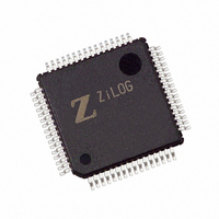
Z8F6422AR020SC2104 Zilog, Z8F6422AR020SC2104 Datasheet - Page 150

Z8F6422AR020SC2104
Manufacturer Part Number
Z8F6422AR020SC2104
Description
IC ENCORE MCU FLASH 64K 64LQFP
Manufacturer
Zilog
Series
Encore!® XP®r
Specifications of Z8F6422AR020SC2104
Core Processor
Z8
Core Size
8-Bit
Speed
20MHz
Connectivity
I²C, IrDA, SPI, UART/USART
Peripherals
Brown-out Detect/Reset, DMA, POR, PWM, WDT
Number Of I /o
46
Program Memory Size
64KB (64K x 8)
Program Memory Type
FLASH
Ram Size
4K x 8
Voltage - Supply (vcc/vdd)
3 V ~ 3.6 V
Data Converters
A/D 12x10b
Oscillator Type
Internal
Operating Temperature
0°C ~ 70°C
Package / Case
64-LQFP
For Use With
269-4678 - KIT DEV FOR Z8F642 MCU 44 PIN269-4677 - KIT DEV FOR Z8F642 MCU 28PIN269-4540 - KIT DEV FOR Z8 ENCORE 16K TO 64K
Lead Free Status / RoHS Status
Contains lead / RoHS non-compliant
Eeprom Size
-
Other names
269-3641
Available stocks
Company
Part Number
Manufacturer
Quantity
Price
- Current page: 150 of 297
- Download datasheet (9Mb)
Table 66. SPI Mode Register (SPIMODE)
PS019921-0308
BITS
FIELD
RESET
R/W
ADDR
Caution:
SPI Mode Register
7
0 = SS input pin is asserted (Low).
1 = SS input is not asserted (High).
If SPI enabled as a Master, this bit is not applicable.
The SPI Mode register
value of the SS pin.
Reserved—Must be 0.
DIAG—Diagnostic Mode Control bit
This bit is for SPI diagnostics. Setting this bit allows the Baud Rate Generator value to be
read using the SPIBRH and SPIBRL register locations.
0 = Reading SPIBRH, SPIBRL returns the value in the SPIBRH and SPIBRL registers
1 = Reading SPIBRH returns bits [15:8] of the SPI Baud Rate Generator; and reading
NUMBITS[2:0]—Number of Data Bits Per Character to Transfer
This field contains the number of bits to shift for each character transfer. For information
on valid bit positions when the character length is less than 8-bits, see SPI Data Register
description.
Reserved
Exercise caution if reading the values while the BRG is counting.
SPIBRL returns bits [7:0] of the SPI Baud Rate Counter. The Baud Rate Counter
000 = 8 bits
001 = 1 bit
010 = 2 bits
011 = 3 bits
100 = 4 bits
101 = 5 bits
110 = 6 bits
111 = 7 bits
High and Low byte values are not buffered.
R
6
DIAG
(Table
5
66) configures the character bit width and the direction and
4
F63H
NUMBITS[2:0]
0
3
R/W
Z8 Encore! XP
2
Product Specification
Serial Peripheral Interface
SSIO
1
®
F64XX Series
SSV
0
136
Related parts for Z8F6422AR020SC2104
Image
Part Number
Description
Manufacturer
Datasheet
Request
R

Part Number:
Description:
Communication Controllers, ZILOG INTELLIGENT PERIPHERAL CONTROLLER (ZIP)
Manufacturer:
Zilog, Inc.
Datasheet:

Part Number:
Description:
KIT DEV FOR Z8 ENCORE 16K TO 64K
Manufacturer:
Zilog
Datasheet:

Part Number:
Description:
KIT DEV Z8 ENCORE XP 28-PIN
Manufacturer:
Zilog
Datasheet:

Part Number:
Description:
DEV KIT FOR Z8 ENCORE 8K/4K
Manufacturer:
Zilog
Datasheet:

Part Number:
Description:
KIT DEV Z8 ENCORE XP 28-PIN
Manufacturer:
Zilog
Datasheet:

Part Number:
Description:
DEV KIT FOR Z8 ENCORE 4K TO 8K
Manufacturer:
Zilog
Datasheet:

Part Number:
Description:
CMOS Z8 microcontroller. ROM 16 Kbytes, RAM 256 bytes, speed 16 MHz, 32 lines I/O, 3.0V to 5.5V
Manufacturer:
Zilog, Inc.
Datasheet:

Part Number:
Description:
Low-cost microcontroller. 512 bytes ROM, 61 bytes RAM, 8 MHz
Manufacturer:
Zilog, Inc.
Datasheet:

Part Number:
Description:
Z8 4K OTP Microcontroller
Manufacturer:
Zilog, Inc.
Datasheet:

Part Number:
Description:
CMOS SUPER8 ROMLESS MCU
Manufacturer:
Zilog, Inc.
Datasheet:

Part Number:
Description:
SL1866 CMOSZ8 OTP Microcontroller
Manufacturer:
Zilog, Inc.
Datasheet:

Part Number:
Description:
SL1866 CMOSZ8 OTP Microcontroller
Manufacturer:
Zilog, Inc.
Datasheet:

Part Number:
Description:
OTP (KB) = 1, RAM = 125, Speed = 12, I/O = 14, 8-bit Timers = 2, Comm Interfaces Other Features = Por, LV Protect, Voltage = 4.5-5.5V
Manufacturer:
Zilog, Inc.
Datasheet:

Part Number:
Description:
Manufacturer:
Zilog, Inc.
Datasheet:


