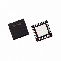
C8051F321R Silicon Laboratories Inc, C8051F321R Datasheet - Page 6

C8051F321R
Manufacturer Part Number
C8051F321R
Description
IC 8051 MCU 16K FLASH 28MLP
Manufacturer
Silicon Laboratories Inc
Series
C8051F32xr
Datasheet
1.C8051F320R.pdf
(256 pages)
Specifications of C8051F321R
Core Processor
8051
Core Size
8-Bit
Speed
25MHz
Connectivity
SMBus (2-Wire/I²C), SPI, UART/USART, USB
Peripherals
Brown-out Detect/Reset, POR, PWM, Temp Sensor, WDT
Number Of I /o
21
Program Memory Size
16KB (16K x 8)
Program Memory Type
FLASH
Ram Size
2.25K x 8
Voltage - Supply (vcc/vdd)
2.7 V ~ 3.6 V
Data Converters
A/D 13x10b
Oscillator Type
Internal
Operating Temperature
-40°C ~ 85°C
Package / Case
28-VQFN Exposed Pad, 28-HVQFN, 28-SQFN, 28-DHVQFN
Lead Free Status / RoHS Status
Contains lead / RoHS non-compliant
Eeprom Size
-
Other names
336-1067-2
- Current page: 6 of 256
- Download datasheet (4Mb)
C8051F320/1
18. ENHANCED SERIAL PERIPHERAL INTERFACE (SPI0) .........................................203
19. TIMERS ...............................................................................................................................217
20. PROGRAMMABLE COUNTER ARRAY (PCA0) .........................................................235
21. C2 INTERFACE ..................................................................................................................253
6
17.1. Enhanced Baud Rate Generation...................................................................................194
17.2.Operational Modes ........................................................................................................195
17.3.Multiprocessor Communications...................................................................................197
18.1. Signal Descriptions........................................................................................................204
18.2.SPI0 Master Mode Operation........................................................................................205
18.3. SPI0 Slave Mode Operation ..........................................................................................207
18.4.SPI0 Interrupt Sources...................................................................................................207
18.5. Serial Clock Timing ......................................................................................................208
18.6.SPI Special Function Registers .....................................................................................210
19.1.Timer 0 and Timer 1......................................................................................................217
19.2. Timer 2 .......................................................................................................................225
19.3.Timer 3 .......................................................................................................................230
20.1.PCA Counter/Timer.......................................................................................................236
20.2. Capture/Compare Modules............................................................................................237
20.3. Watchdog Timer Mode..................................................................................................246
20.4. Register Descriptions for PCA ......................................................................................248
21.1. C2 Interface Registers ...................................................................................................253
17.2.1. 8-Bit UART .........................................................................................................195
17.2.2. 9-Bit UART .........................................................................................................196
18.1.1. Master Out, Slave In (MOSI) ..............................................................................204
18.1.2. Master In, Slave Out (MISO) ..............................................................................204
18.1.3. Serial Clock (SCK) ..............................................................................................204
18.1.4. Slave Select (NSS)...............................................................................................204
19.1.1. Mode 0: 13-bit Counter/Timer.............................................................................217
19.1.2. Mode 1: 16-bit Counter/Timer.............................................................................218
19.1.3. Mode 2: 8-bit Counter/Timer with Auto-Reload .................................................219
19.1.4. Mode 3: Two 8-bit Counter/Timers (Timer 0 Only) ...........................................220
19.2.1. 16-bit Timer with Auto-Reload ...........................................................................225
19.2.2. 8-bit Timers with Auto-Reload............................................................................226
19.2.3. USB Start-of-Frame Capture ...............................................................................227
19.3.1. 16-bit Timer with Auto-Reload ...........................................................................230
19.3.2. 8-bit Timers with Auto-Reload............................................................................231
19.3.3. USB Start-of-Frame Capture ...............................................................................232
20.2.1. Edge-triggered Capture Mode .............................................................................238
20.2.2. Software Timer (Compare) Mode........................................................................239
20.2.3. High Speed Output Mode ....................................................................................240
20.2.4. Frequency Output Mode ......................................................................................241
20.2.5. 8-Bit Pulse Width Modulator Mode ....................................................................242
20.2.6. 16-Bit Pulse Width Modulator Mode ..................................................................244
20.3.1. Watchdog Timer Operation .................................................................................246
20.3.2. Watchdog Timer Usage .......................................................................................247
Rev. 1.1
Related parts for C8051F321R
Image
Part Number
Description
Manufacturer
Datasheet
Request
R
Part Number:
Description:
SMD/C°/SINGLE-ENDED OUTPUT SILICON OSCILLATOR
Manufacturer:
Silicon Laboratories Inc
Part Number:
Description:
Manufacturer:
Silicon Laboratories Inc
Datasheet:
Part Number:
Description:
N/A N/A/SI4010 AES KEYFOB DEMO WITH LCD RX
Manufacturer:
Silicon Laboratories Inc
Datasheet:
Part Number:
Description:
N/A N/A/SI4010 SIMPLIFIED KEY FOB DEMO WITH LED RX
Manufacturer:
Silicon Laboratories Inc
Datasheet:
Part Number:
Description:
N/A/-40 TO 85 OC/EZLINK MODULE; F930/4432 HIGH BAND (REV E/B1)
Manufacturer:
Silicon Laboratories Inc
Part Number:
Description:
EZLink Module; F930/4432 Low Band (rev e/B1)
Manufacturer:
Silicon Laboratories Inc
Part Number:
Description:
I°/4460 10 DBM RADIO TEST CARD 434 MHZ
Manufacturer:
Silicon Laboratories Inc
Part Number:
Description:
I°/4461 14 DBM RADIO TEST CARD 868 MHZ
Manufacturer:
Silicon Laboratories Inc
Part Number:
Description:
I°/4463 20 DBM RFSWITCH RADIO TEST CARD 460 MHZ
Manufacturer:
Silicon Laboratories Inc
Part Number:
Description:
I°/4463 20 DBM RADIO TEST CARD 868 MHZ
Manufacturer:
Silicon Laboratories Inc
Part Number:
Description:
I°/4463 27 DBM RADIO TEST CARD 868 MHZ
Manufacturer:
Silicon Laboratories Inc
Part Number:
Description:
I°/4463 SKYWORKS 30 DBM RADIO TEST CARD 915 MHZ
Manufacturer:
Silicon Laboratories Inc
Part Number:
Description:
N/A N/A/-40 TO 85 OC/4463 RFMD 30 DBM RADIO TEST CARD 915 MHZ
Manufacturer:
Silicon Laboratories Inc
Part Number:
Description:
I°/4463 20 DBM RADIO TEST CARD 169 MHZ
Manufacturer:
Silicon Laboratories Inc


